

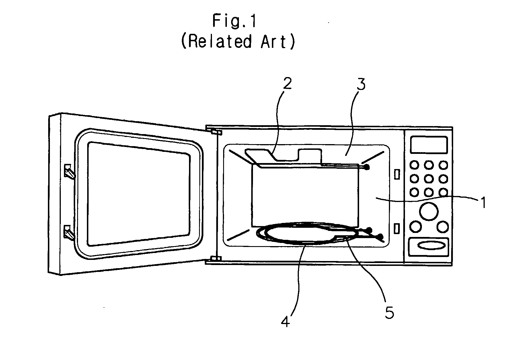
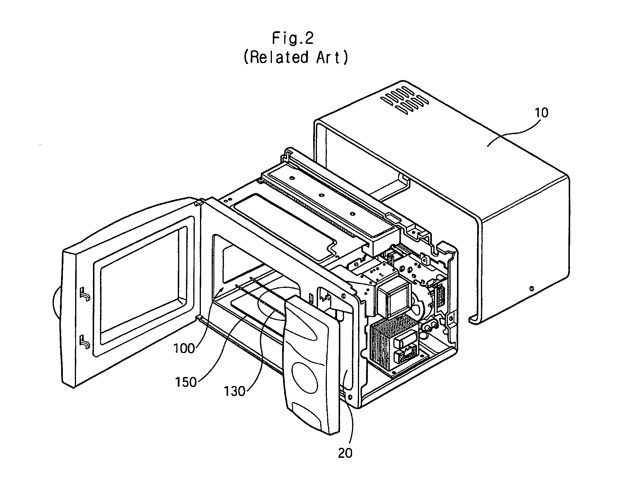
Heating apparatus of microwave oven and food heating method
- Summary
- Abstract
- Description
- Claims
- Application Information
AI Technical Summary
Benefits of technology
Problems solved by technology
Method used
Image

Examples
Embodiment Construction
[0030] Hereinafter, preferred embodiments of the present invention will be described in detail with reference to accompanying drawings.
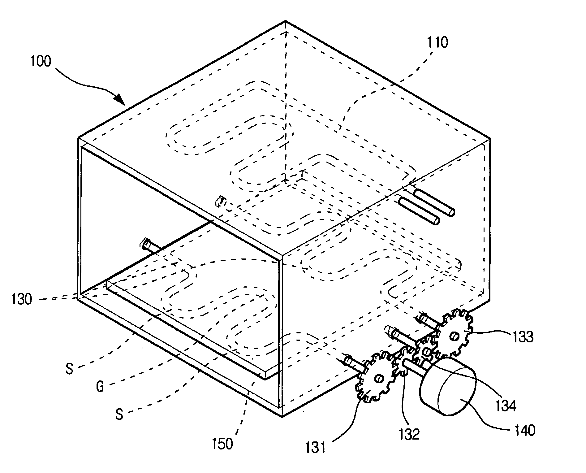
[0031]FIG. 2 is a perspective view of a microwave oven according to the present invention. FIG. 3 is a perspective view of a heating apparatus of a microwave oven according to the present invention.
[0032] Referring to FIGS. 2 and 3, the microwave oven includes an outer casing 10, a cavity 100, a tray 150, and an electronic components room 20. The cavity 100 forms a cooking space in the outer casing 10. The tray 150 is placed on the lower portion of the cavity 100 to receive a food thereon. The electronic components room 20 is disposed at a side inside the outer casing 10 to accommodate various components necessary to operate the microwave oven.
[0033] Inside the electronic components room 20, installed are a magnetron for generating microwave, a wave guide for guiding the microwave generated by the magnetron to a cooking chamber, a high voltage tra...
PUM
 Abstract
Description
Claims
Application Information