Heat recovery unit and heat recovery system of building utilizing it

a heat recovery unit and heat recovery technology, applied in ventilation systems, lighting and heating apparatus, heating types, etc., can solve the problems of increasing concern for ventilation in housing, inefficient thermal energy emission during ventilation of air-conditioned housing, and the reduction of cosub>2 /sub>emission, etc., to achieve high-efficiency thermal conduction materials and reduce temperature differences

Inactive Publication Date: 2005-06-30
PALM +1
View PDF12 Cites 53 Cited by
  • Summary
  • Abstract
  • Description
  • Claims
  • Application Information

AI Technical Summary

Benefits of technology

[0008] A highly efficient thermal conduction material is used as the medium, and heat is conducted without transferring via the medium. Such configuration allows reduction in difference in temperature between the top and the bottom of a room or between rooms.

Problems solved by technology

In particular, a problem of reduction in CO2 emission has come under close scrutiny after ratification of the Kyoto Protocol.
On the other hand, with ordinary housing, a concern for ventilation in housing has grown due to health problems.
However, good ventilation leads to inefficient thermal energy emission during ventilation of air-conditioned housing.

Method used


Image

  • Heat recovery unit and heat recovery system of building utilizing it
  • Heat recovery unit and heat recovery system of building utilizing it
  • Heat recovery unit and heat recovery system of building utilizing it

Examples


Embodiment Construction

[0017] An embodiment of the present invention is described while referencing the drawings.

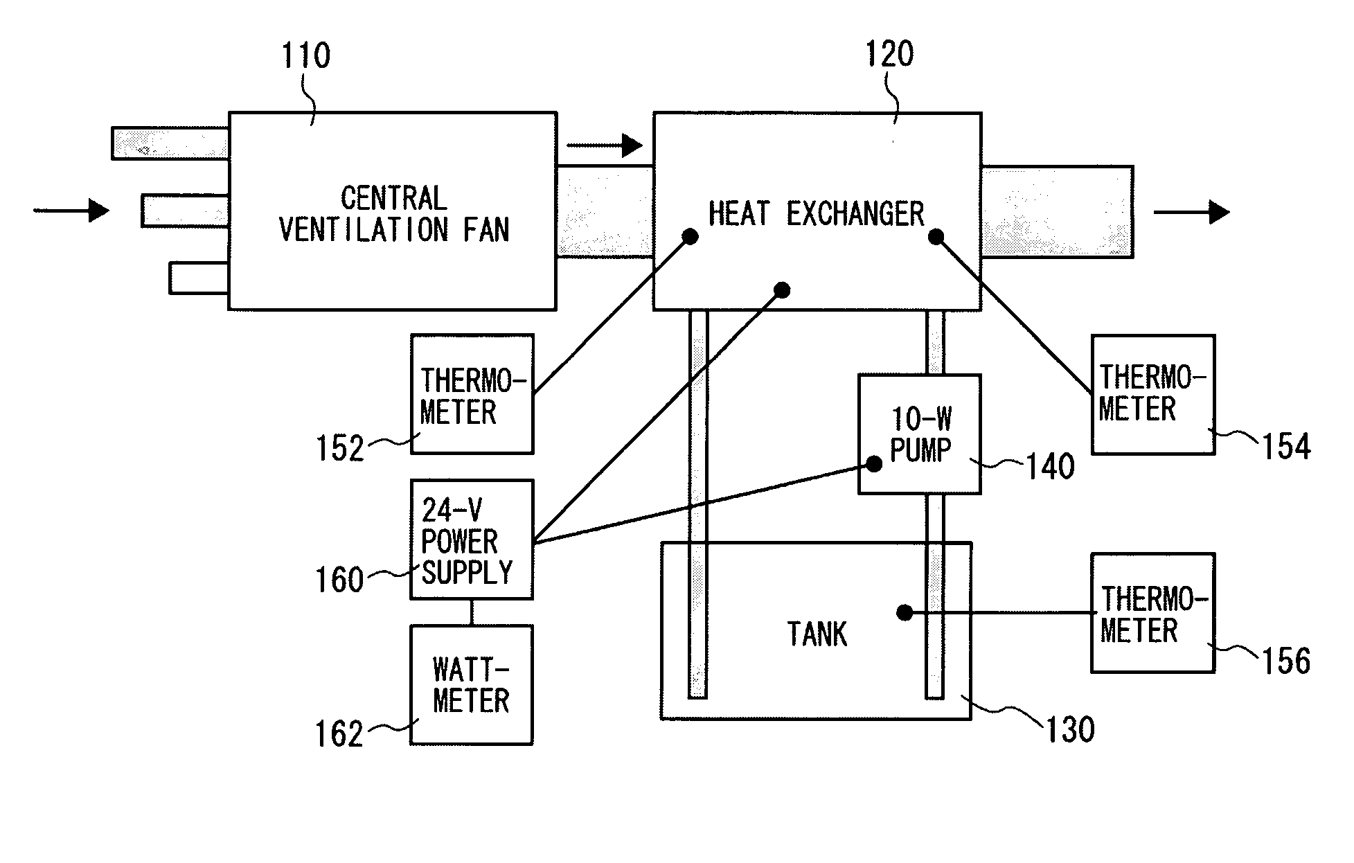
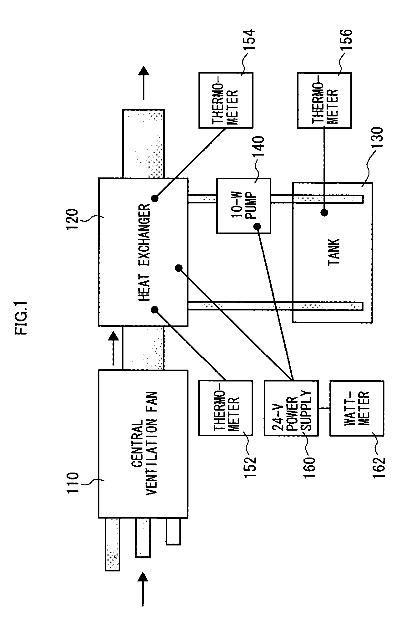
[0018]FIG. 1 shows an entire configuration of a heat recovery device which conducts ventilation heat to a medium. A case of heating each room in a building using the device shown in FIG. 1 is described. The heat recovery device of the embodiment uses water as a heat medium. The heat medium for the heat recovery device may be any fluid: liquid such as oil, gas such as air, solid, or a mixture thereof. On the other hand, to be described later, there is a case where fluid is not used as a heat medium.

[0019] In FIG. 1, air emitted from each room for ventilation is collected through a central ventilation fan 110. The central ventilation fan 110 is connected to a heat exchanger 120 via a ventilation pipe. Air collected in the central ventilation fan 110 is emitted from the heat recovery device after recovering heat from heated exhaust air by the heat exchanger 120. On the other hand, the heat excha...


PUM


Abstract

The objective of the present invention is to provide a system which allows efficient air-conditioning heat recovery during ventilation and is applicable to ordinary housing. In order to achieve the above objective, a central ventilation fan 110 is connected to a heat exchanger 120 via a ventilation pipe. Air collected in the central ventilation fan 110 is emitted via the heat exchanger 120 from a device after recovering heat from heated exhaust air from each room by the heat exchanger 120. On the other hand, the heat exchanger 120 is connected to a tank 130 via a water suction/drainage pipe. Water drawn up from the tank 130 by a pump 140 is heated by the heat exchanger 120 and then returned to the tank 130 again. The heat exchanger 120 uses the Peltier device to cool the exhaust air from the central ventilation fan 110, and heat water in the tank 130 at the same time, thereby efficiently transferring air heat from each room to water. Efficient transfer of heat using the Peltier device allows a higher temperature of the water from the heat exchanger than the exhaust air temperature.

Description

TECHNICAL FIELD [0001] The present invention relates to a heat recovery device and a building heat recovery system using the same to efficiently recover air conditioning heat during ventilation of buildings. BACKGROUND OF THE INVENTION [0002] Urgent solutions for environmental issues have been desired. In particular, a problem of reduction in CO2 emission has come under close scrutiny after ratification of the Kyoto Protocol. Energy saving must be promoted in every field throughout the nation in order to reduce CO2 emission. Therefore, energy saving is required even for heating and cooling in small buildings, more specifically, in ordinary housing. [0003] On the other hand, with ordinary housing, a concern for ventilation in housing has grown due to health problems. However, good ventilation leads to inefficient thermal energy emission during ventilation of air-conditioned housing. [0004] Consequently, a system which allows efficient air-conditioning heat recovery during ventilation...

Claims


Application Information

Patent Timeline
Patent Type & Authority Applications(United States)
IPC IPC(8): F24F5/00F24F12/00F25B21/02H01L35/30
CPCF24F5/0042F24F5/0089H01L35/30F25B21/02F25B2321/0252F24F12/00Y02P80/15H10N10/13
Inventor YAMAMOTO, HIDEYO
Owner PALM
Why Eureka
Try Eureka