Tissue homogenizer

Active Publication Date: 2005-06-30
IND TECH RES INST
View PDF3 Cites 52 Cited by
  • Summary
  • Abstract
  • Description
  • Claims
  • Application Information

AI Technical Summary

Benefits of technology

[0007] The present invention successively cuts, filters, and collects finally the homogenized tissue pieces in a sealed device. The present invention produces homogenized tissue pieces at lower cost in a shorter time, and prevents tissue waste. As well,

Problems solved by technology

When cut by scalpel blade, however, the tissue piece is easily polluted and difficult to collect.
This conventional method of cutting tissue (homogenizing) wasteful; and when primary tissue

Method used


Image

  • Tissue homogenizer
  • Tissue homogenizer
  • Tissue homogenizer

Examples


Embodiment Construction

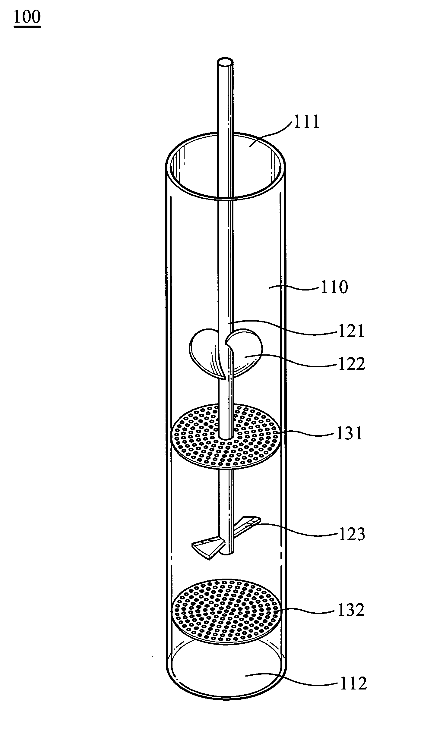
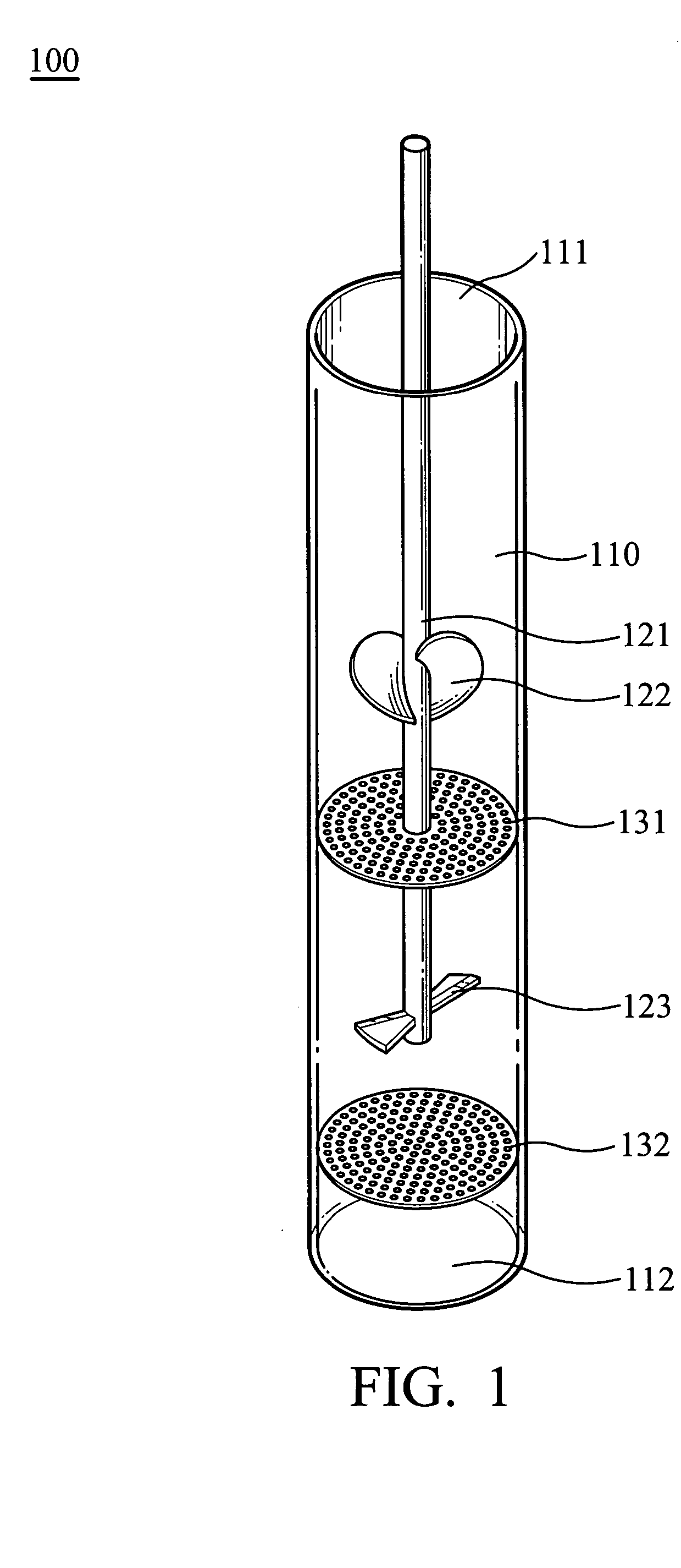
[0013]FIG. 1 shows the main structure of the tissue homogenizer 100 of the present invention comprising a first chamber 110, a driving mechanism 121, a pair of vanes (directing mechanism) 122, a pair of blades 123, a first filter 131 and a second filter 132. The first chamber 110 has a first opening 111 and a second opening 112. The driving mechanism 121 extends into the first chamber 110 from the first opening 111. The vanes 122 and the blades 123 are disposed on the driving mechanism 121 in the first chamber 110. The first filter 131 is disposed between the vanes 122 and the blades 123. The second filter 132 is disposed between the second opening 112 and the blades 123.

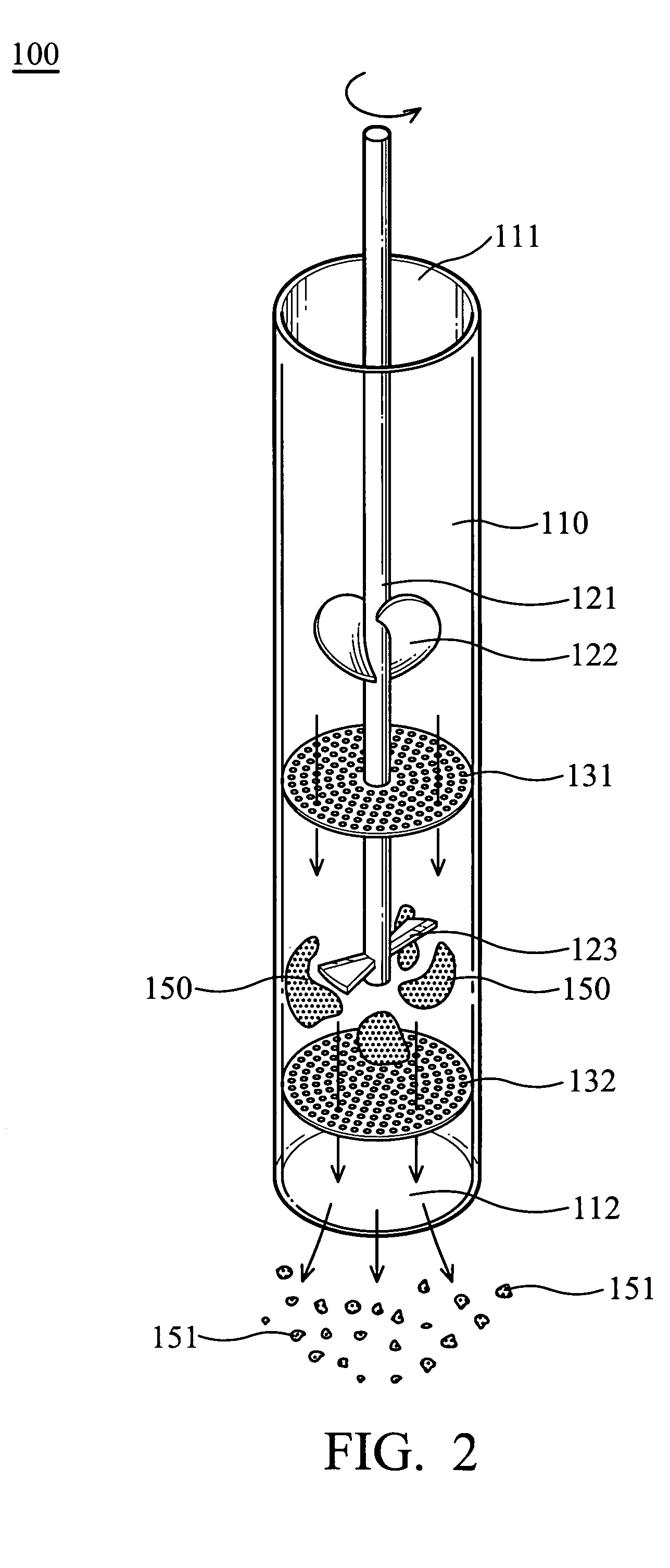
[0014]FIG. 2 shows the tissue homogenizer 100 homogenizing tissue pieces 150. The tissue pieces 150 are disposed between the first filter 131 and the second filter 132. The first filter 131 restricts the distribution of the tissue pieces 150. The first chamber 110 is filled with a fluid. The driving mechanism 121 i...


PUM


Abstract

A tissue homogenizer. The tissue homogenizer comprises a first chamber, a pair of blades, a first filter and a second filter. The first chamber has a first opening and a second opening. The blades are disposed in the first chamber. The first filter is disposed in the first chamber between the first opening and the blades. The second filter is disposed in the first chamber between the second opening and the blades. A tissue piece is placed between the first filter and the second filter cut by the blade, and moved by a fluid through the second filter to generate homogenized tissue pieces.

Description

BACKGROUND OF THE INVENTION [0001] 1. Field of the Invention [0002] The present invention relates to a tissue homogenizer and in particular to a tissue homogenizer for homogenizing live histiocyte. [0003] 2. Description of the Related Art [0004] In conventional culture preparation, a tissue piece is cut in a culture dish by scalpel blade, soaked in protease enzyme to separate cells from cytoplasm, and applied to a culture experiment. When cut by scalpel blade, however, the tissue piece is easily polluted and difficult to collect. This conventional method of cutting tissue (homogenizing) wasteful; and when primary tissue is limited, may prevent successful culture. [0005] U.S. Pat. No. 4,874,137 teaches homogenization of tissue piece by ultrasonic wave. U.S. Pat. No. 4,509,695 teaches homogenization of tissue which is originally cooled by liquid nitrogen and then pulverized. U.S. Pat. Nos. 5,829,696, 5,533,683, 4,525,395 and 4,509,695 teach homogenization of tissue piece by pulverizin...

Claims


Application Information

Patent Timeline
IPC IPC(8): A47J17/00
CPCC12M45/02G01N2001/2866G01N1/286
Inventor LIAO, CHUN-JENHSU, HUA-CHUNHSU, KO-CHUNCHEN, DA-PANLIN, MEI-CHIAO
Owner IND TECH RES INST
Why Eureka
Try Eureka