Continuous molding method and molding apparatus for surface fastener

a molding method and surface fastener technology, applied in the field of continuous molding method of surface fasteners, can solve the problems of inability to emboss the surface of the flat base member of the aforementioned molded surface fastener inability to emboss the surface of the flat base member at one time in the formation region of the rotation roller, and inability to emboss the surface of the flat base member at one time in th

Inactive Publication Date: 2005-06-30
YKK CORP
View PDF12 Cites 6 Cited by
  • Summary
  • Abstract
  • Description
  • Claims
  • Application Information

AI Technical Summary

Benefits of technology

[0012] Accordingly, an object of the present invention is to solve the above-described problems and then, provide a molding method and molding apparatus, effective and cheap, for a molded surface fastener required to be directly or indirectly bonded with or fit to an mounting object, capable of increasing a bonding strength or a friction force regardless of a configuration of a bonding surface.
[0019] According to the method of the present invention, by forming the fine unevenness in the rear surface of the flat base member of the molded surface fastener, a bonding area increases, so that a bonding strength with an adhesive agent or a foamed resin is intensified remarkably. Because a clear uneven surface can be generated by using air or water which is cheap and easy to obtain as the refrigerant flowing through the extrusion die, it is not necessary to use any special refrigerant.
[0020] As described above, the rear surface of the flat base member can be cooled aggressively in the initial period of molding of the surface fastener with a simple structure in which a refrigerant passage extending in the width direction is formed inside the extrusion die located downstream in the rotation direction of the die wheel from the extruding port in the extrusion die so as to feed the refrigerant, and a number of fine unevenness is formed in the rear surface of the flat base member by cooling. Therefore, it is not necessary to provide any mechanical unevenness forming means such as an emboss roller.
[0022] In the molding apparatus of the present invention, one or more grooves extending in the rotation direction of the die wheel whose ends are open to the extruding port are formed in an opposing face in the rotation direction of the die wheel downstream from the extruding port in the extrusion die outside of the refrigerant passage. The section of this groove is triangular, U-shaped or inverted T shaped, and a large uneven surface extending continuously in a length direction and having a zigzag shaped section can be formed on the rear surface of the flat base member by this groove portion. A bonding performance and friction with adhesive agent or elastomer foamed resin can be increased by this continuous uneven surface.

Problems solved by technology

However, mechanical embossing of the surface of the flat base member of the aforementioned molded surface fastener at one time in a base member formation region with the rotation roller is impossible as long as the continuous molding methods as mentioned in U.S. Pat. Nos. 5,800,760 and 5,945,193 are adopted.
Especially, if the anchor pieces composed of inverted-T shaped engaging row or hook pieces are formed on a surface opposite to an engaging element formation surface as described in the aforementioned U.S. patens, not only the embossing but also any mechanical processing is impossible.
Even if the surface of the base member opposite to the engaging element formation face of the molded surface fastener is smooth, it is necessary to provide with an emboss roller separately at downstream side from the molding roller or in an opposing condition to the peripheral surface of the molding roller, because the embossing in the base member formation region is impossible as described above, as long as the continuous molding method is adopted.

Method used


Image

  • Continuous molding method and molding apparatus for surface fastener
  • Continuous molding method and molding apparatus for surface fastener
  • Continuous molding method and molding apparatus for surface fastener

Examples


first embodiment

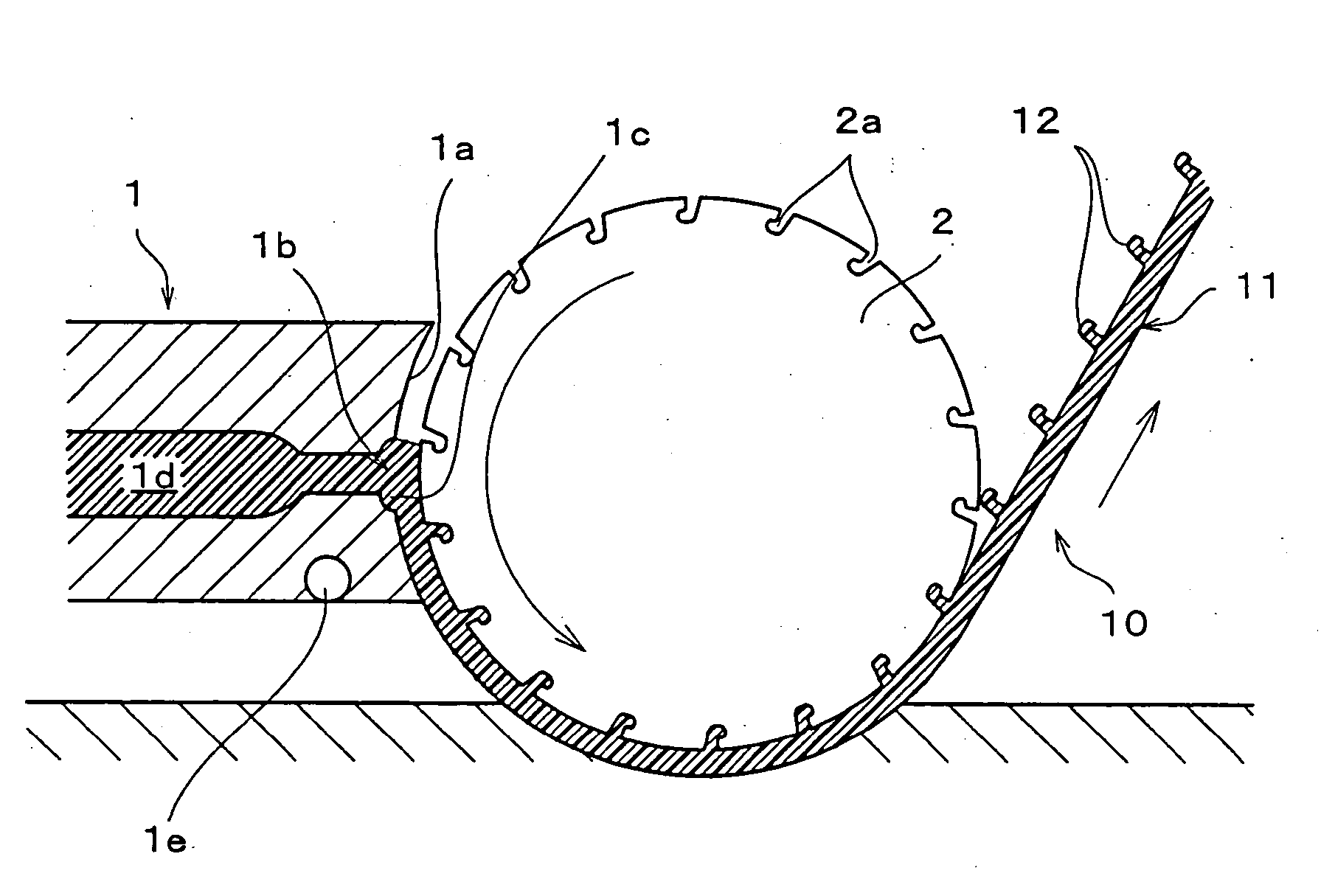
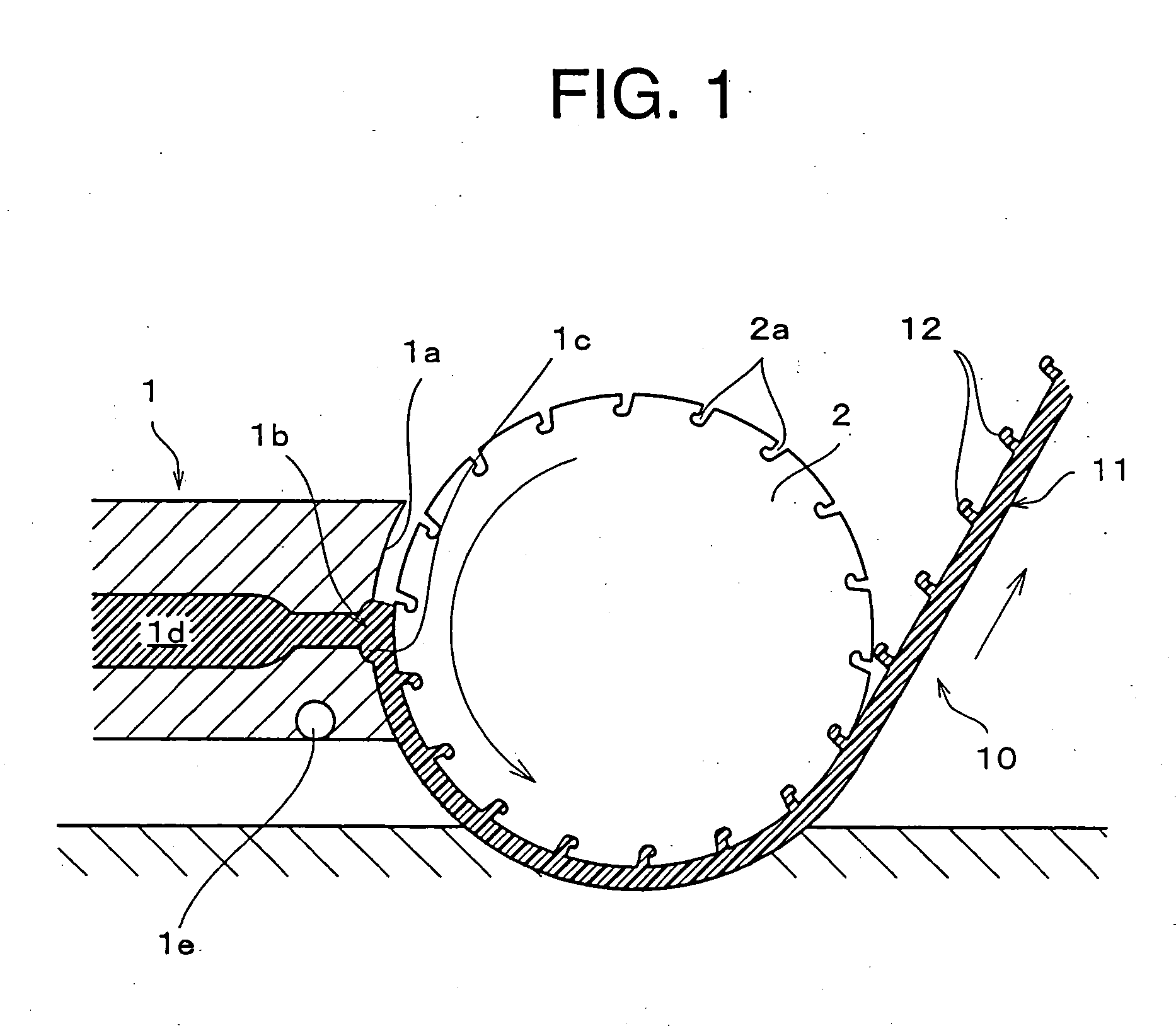
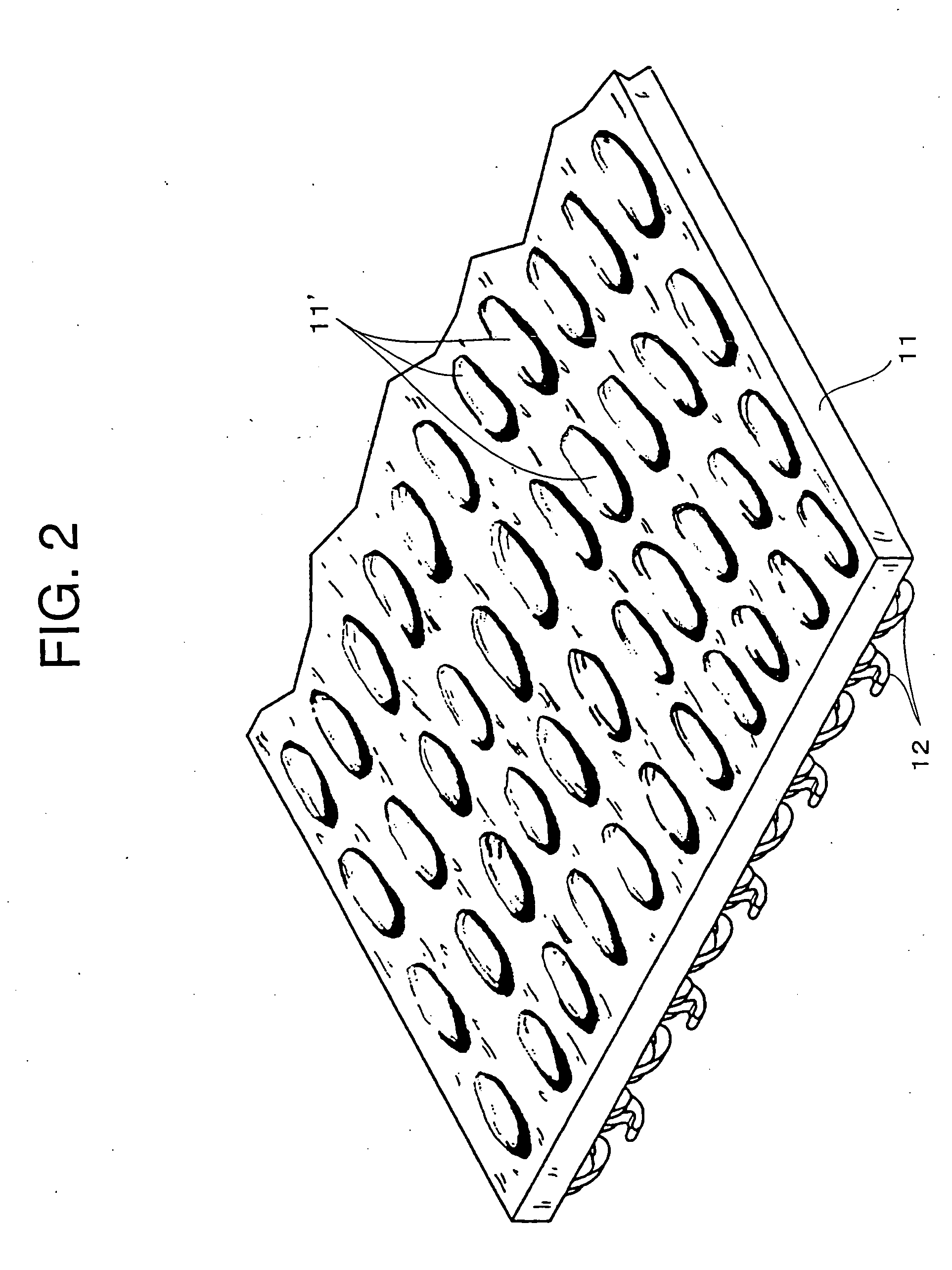
[0031]FIG. 1 is a longitudinal sectional view showing a continuous molding apparatus and molding procedure for a molded surface fastener according to a first embodiment of the present invention. Although this embodiment adopts a hook piece as an engaging element formed on a surface of a base member, this embodiment is not restricted to this configuration and various types such as mushroom type or double leaves type may be adopted. The molded surface fastener of this embodiment is an ordinary surface fastener and no special notch or engaging row is formed on a rear surface of a flat base member having no engaging elements.

[0032] In this figure, reference numeral 1 denotes a (continuous) extrusion die, and a front end of the extrusion die 1 is formed as a circular face 1a having such a curvature which allows a predetermined gap to be formed with respect to a round peripheral surface of a die wheel 2 described later. This extrusion die 1 is constituted of a T type die, and as shown in...

second embodiment

[0038] Next, a second embodiment of the present invention will be described. FIG. 3 shows a continuous molding apparatus for a molded surface fastener and its molding procedure according to the second embodiment of the present invention. FIG. 4 is a sectional view taken along a line IV-IV in FIG. 3. In these figures, what is largely different from the first embodiment exists in a shape of the circular face 1a below the resin extruding port 1b in the extrusion die 1. The other configuration is not substantially different from the first embodiment. Hence, in the following description, different portions from the first embodiment will be stated specifically while the same components will be explained briefly.

[0039] According to this embodiment, as shown in FIG. 4, plural concave groove forming paths 1f are formed in parallel in the circular face 1a located below the molten resin reservoir 1c formed on the front surface of the extrusion die 1 such that they extend along a circularity. ...

third embodiment

[0042]FIG. 6 schematically shows a section of a continuous molding portion of a molded surface fastener according to a third embodiment of the present invention. This embodiment concerns a continuous molding apparatus for a molded surface fastener with an engaging row which is interposed between a mounting frame and a sheet material in order to attach the sheet material such as a curtain to the mounting frame, and its molding procedure.

[0043] Although this embodiment is different from the second embodiment in terms of dimension, the structure of the major components and its molding procedure are not largely different from the first and second embodiments. What is different from the first and second embodiments is that one or more engaging row forming paths 1h having an inverted-T shaped section one end of which communicates with the resin extruding port 1b while the other end is open to an end in the rotation direction of the die wheel of the circular face 1a are formed in the cent...


PUM

PropertyMeasurementUnit
melting pointaaaaaaaaaa
timeaaaaaaaaaa
friction coefficientaaaaaaaaaa

Abstract

The invention provides a molding method and molding apparatus, effective and cheap, for a surface fastener to be directly / indirectly bonded with / fit to an mounting object, capable of increasing the bonding strength or friction force regardless of the configuration of a bonding surface, wherein molten resin is discharged continuously from a resin extruding port of an extrusion die to a peripheral surface of a die wheel having hook piece forming cavities therein for forming hook pieces in the hook piece forming cavities while forming a flat base member at a gap between the extrusion die and the die wheel, the rear surface of a surface fastener without engaging elements is cooled by feeding refrigerant through a refrigerant passage formed in the extrusion die below the resin extruding port, surface sinks are formed in the entire rear surface for increasing bonding area, thereby increasing bonding strength and friction force.

Description

BACKGROUND OF THE INVENTION [0001] 1. Field of the Invention [0002] The present invention relates to a continuous molding method for a surface fastener for integrally molding a number of engaging elements erected on a surface of a flat base member at the same time when the flat base member is formed by continuous extrusion with thermoplastic resin, and a molding apparatus therefor. [0003] 2. Description of the Related Art [0004] According to a conventionally known method of manufacturing a molded surface fastener, a thermoplastic resin material in a molten state is extruded continuously from an extrusion die to a peripheral surface of a die wheel having a number of engaging element forming cavities in its peripheral surface and rotating in a single direction so as to mold a flat base member between the peripheral surface of the die wheel and the front surface of the extrusion die at the same time of forming engaging elements by the engaging element forming cavities on the rotating d...

Claims


Application Information

Patent Timeline
Patent Type & Authority Applications(United States)
IPC IPC(8): A44B18/00B29C43/22B29C48/35B29D11/00
CPCA44B18/0049B29C43/222B29L2031/729B29C43/46H01L2924/0002B29C2043/461H01L2924/00A44B18/00B29C43/22B29D5/00
Inventor MINATO, TSUYOSHI
Owner YKK CORP
Why Eureka
Try Eureka