
Driver IC and inspection method for driver IC and output device

Inactive Publication Date: 2005-06-30
SEIKO EPSON CORP
View PDF3 Cites 0 Cited by
  • Summary
  • Abstract
  • Description
  • Claims
  • Application Information

AI Technical Summary

Benefits of technology

[0012] wherein each of the signal switch circuits switches between a first state in which a signal from an upstream side of the signal path is allowed to pass through the

Problems solved by technology

Therefore, since the pad-to-pad leakage test must be manually performed corresponding to the type of driver IC taking the output pad arrangement into consideration, the operation is complicated and a considerable amount of time is required for programming.

Method used


Image

  • Driver IC and inspection method for driver IC and output device
  • Driver IC and inspection method for driver IC and output device
  • Driver IC and inspection method for driver IC and output device

Examples


Embodiment Construction

[0046] The following embodiments of the present invention have been achieved in view of the above-described problems, and may provide a driver IC which has a function of supplying inspection signals inside the IC without receiving various inspection signals from outside, and an inspection method for the driver IC.

[0047] The embodiments may also provide an inspection method for an output device driven by a driver IC by using an inspection function of the driver IC.

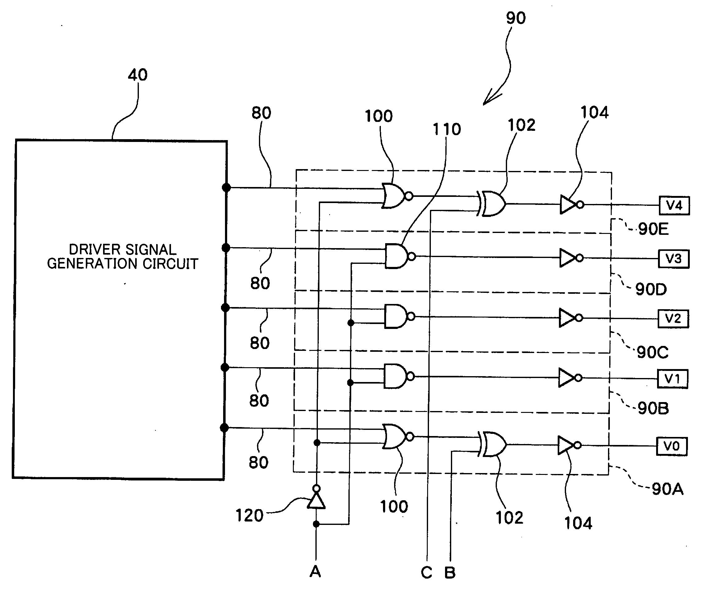
[0048] According to one embodiment of the present invention, there is provided a driver IC comprising: [0049] a plurality of output pads; and [0050] a plurality of signal switch circuits, each of the signal circuits being provided on one of signal paths respectively connected to the output pads, [0051] wherein each of the signal switch circuits switches between a first state in which a signal from an upstream side of the signal path is allowed to pass through the signal switch circuit and a second state in which a level p...


PUM


Abstract

A driver IC including: a plurality of output pads; and a plurality of signal switch circuits, each of the signal circuits being provided on one of signal paths respectively connected to the output pads, wherein each of the signal switch circuits switches between a first state (or a use state) in which a signal from an upstream side of the signal path is allowed to pass through the signal switch circuit and a second state (or an inspection state) in which a level pattern of signals from the output pads is fixed to an inspection level pattern, according to a control signal.

Description

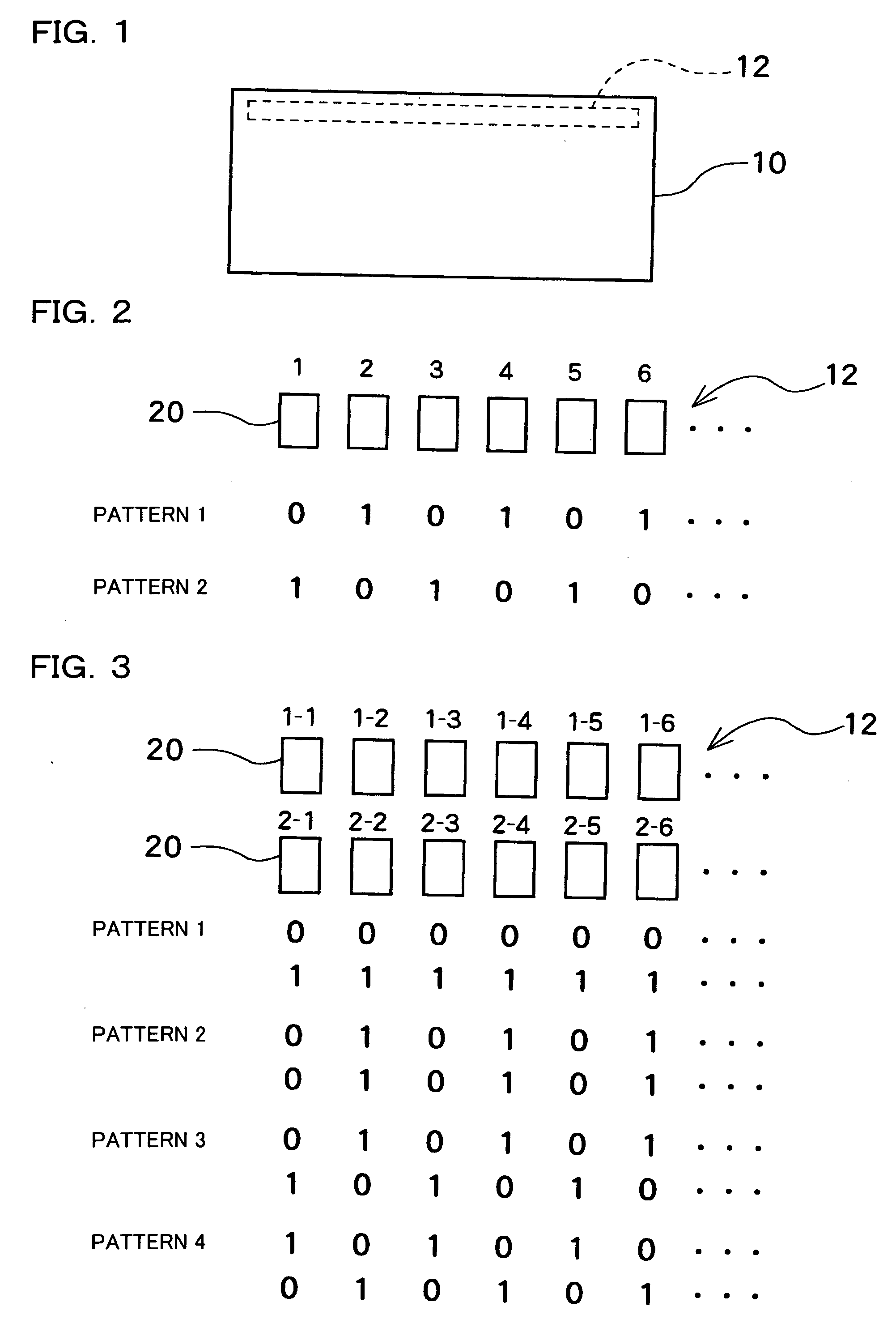
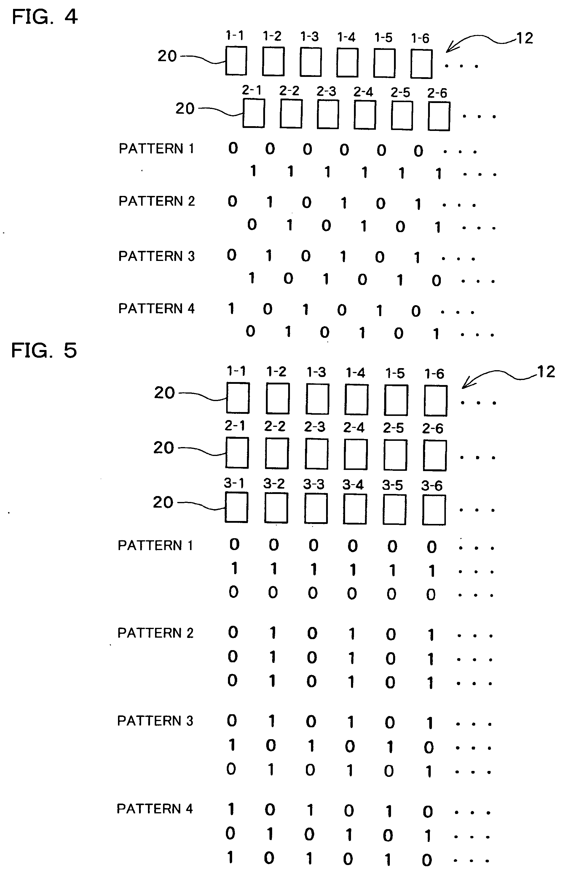
[0001] Japanese Patent Application No. 2003-429405, filed on Dec. 25, 2003, is hereby incorporated by reference in its entirety. BACKGROUND OF THE INVENTION [0002] The present invention relates to a driver IC having an inspection function, and an inspection method for the driver IC. The present invention also relates to an inspection method for an output device driven by a driver IC having an inspection function, such as a display device including a liquid crystal, organic EL, or LED, or a printer. [0003] A driver IC includes a number of output pads (banks) at least along the direction of the long side of an IC chip. The driver IC is subjected to various types of inspection in a state formed on a semiconductor wafer or in a completed state after packaging. The inspection is performed by supplying an inspection signal to the driver IC after supplying an inspection command, and monitoring the output from the driver IC. [0004] As an example of this type of inspection, a pad-to-pad leak...

Claims


Application Information

Patent Timeline
IPC IPC(8): G01R31/28G01R31/317G09G3/20H01L21/822H01L27/04H03B1/00
CPCG01R31/31715
Inventor OTA, YUSUKE
Owner SEIKO EPSON CORP
Learn More