Transmitting and receiving apparatus and method in adaptive array antenna system capable of real-time error calibration

a technology of adaptive array antenna and receiver, applied in the direction of antennas, instruments, electrical equipment, etc., can solve the problems of complex hardware, reduced effect of received signals, system performance deterioration, etc., and achieve the effect of reducing calibration time interval and reducing interference between transmitting and receiving signals

Active Publication Date: 2005-06-30
ELECTRONICS & TELECOMM RES INST
View PDF6 Cites 80 Cited by
  • Summary
  • Abstract
  • Description
  • Claims
  • Application Information

AI Technical Summary

Benefits of technology

[0010] It is an advantage of the present invention to provide a transmitting and receiving apparatus and method in an adaptive array antenna system capable of real-time RF calibration, by which relative gains and phases of the array transmitter and receiver are slowly varied with time to reduce a calibration time interval, thereby reducing interference to the transmit and received signals.
[0011] In one aspect of the present invention, a receiving apparatus in an adaptive array antenna system capable of real-time calibration comprises a calibration signal generator generating an RF CW signal; a calibration signal injector injecting the calibration signal output from the calibration signal generator into each channel of the array receiver; an array receiver down-converting the RF calibration signal and the antenna signals to digital complex baseband signals; a calibration controller estimating the transfer function of the array receiver to calculate the calibration coefficients, and controlling the calibration signal power; and an error corrector correcting the different transfer function of the array receiver using the calibration coefficients output from the calibration controller.
[0012] The calibration signal injector includes a power divider dividing the calibration signal generated by the calibration signal generator, and a plurality of couplers combining the RF signals received through the array antenna with the calibration signals output from the power divider, respectively, and outputting the combined signals to the array receiver.
[0013] The array receiver includes a plurality of down-converters down-converting the RF signals to intermediate frequency band signals; a plurality of variable amplifiers respectively controlling gains of each receive channel; a plurality of analog-to-digital converters respectively sampling the signals output from the variable amplifiers; a plurality of digital I / Q demodulators respectively demodulating the signals sampled by the analog-to-digital converters into complex baseband signals and outputting the complex baseband signals to the error corrector; a power estimator estimating the power of the signals sampled by the analog-to-digital converters; and a gain control value calculator calculating the gain control value of the variable amplifiers on the basis of an error between the mean value of receiving power, calculated by the power estimator, and a predetermined reference value.
[0014] The error corrector includes a plurality of complex multipliers that multiply the RF signals output from the array receiver by the calibration coefficients output from the calibration controller, and output the resultant signals to the beam former, respectively.
[0015] The calibration controller includes a plurality of mean estimators adding up the plurality of signals output from the array receiver for a predetermined period of time to estimate mean values for the signals, respectively; a calibration coefficient calculator calculating the calibration coefficients for the plurality of paths on the basis of the mean values estimated by the mean estimators and outputting the calibration coefficients to the error corrector; and a calibration signal power controller calculating a calibration signal ratio (CSR) on the basis of the mean values estimated by the plurality of mean estimators, and outputting a control signal to the calibration signal generator for controlling the power of the calibration signal such that the calculated CSR converges on a predetermined reference value.

Problems solved by technology

However, an actual array receiving system has different amplitude and phase transfer functions for each array channel because of analog device characteristics comprising the receiver and other causes.
Though the effect of received signals can be reduced when the power of the calibration signal is increased, the system performance will be deteriorated because the calibration signal is interference to the antenna signals.
However, the matched filtering requires exact timing information and the multiplication operations to result in complicated hardware.

Method used


Image

  • Transmitting and receiving apparatus and method in adaptive array antenna system capable of real-time error calibration
  • Transmitting and receiving apparatus and method in adaptive array antenna system capable of real-time error calibration
  • Transmitting and receiving apparatus and method in adaptive array antenna system capable of real-time error calibration

Examples


Embodiment Construction

[0040] In the following detailed description, only the preferred embodiment of the invention has been shown and described, simply by way of illustration of the best mode contemplated by the inventor(s) of carrying out the invention. As will be realized, the invention is capable of modification in various obvious respects, all without departing from the invention. Accordingly, the drawings and description are to be regarded as illustrative in nature, and not restrictive.

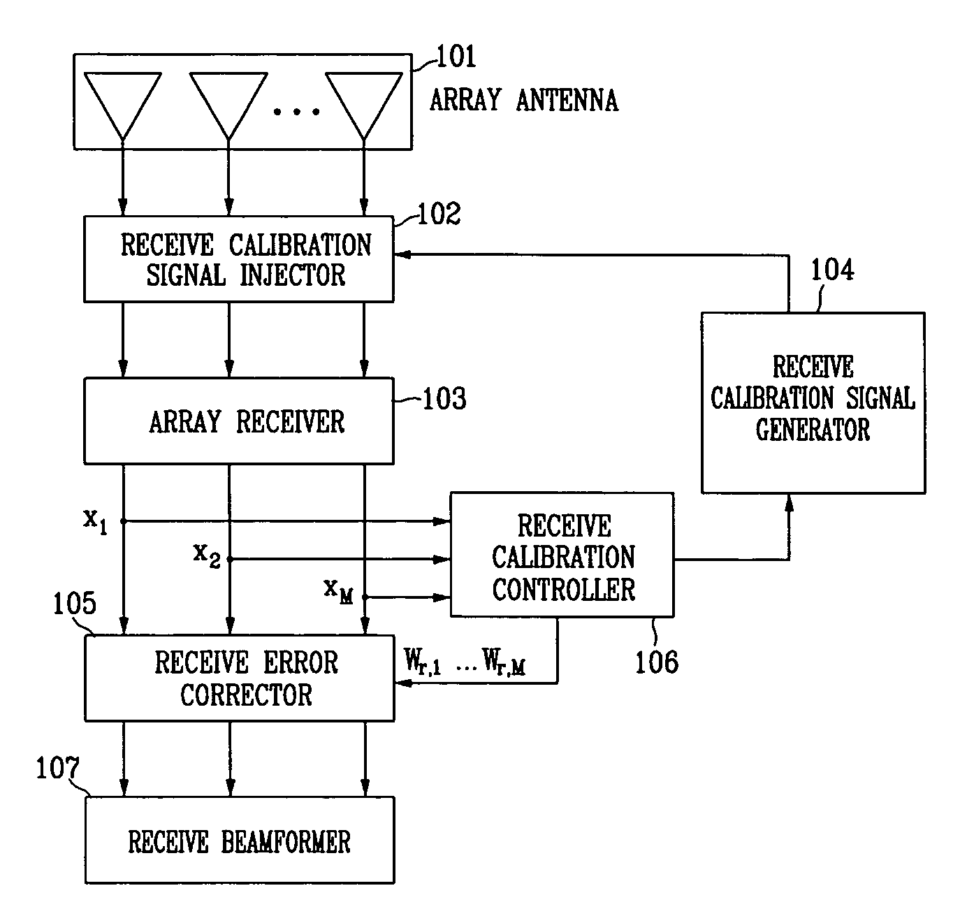
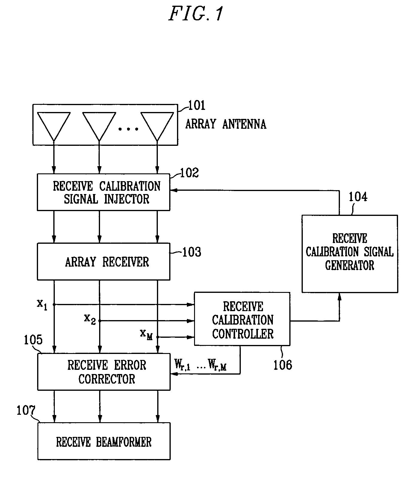
[0041]FIG. 1 is a block diagram of an array receiver system capable of real-time receive calibration according to an embodiment of the present invention. Referring to FIG. 1, the array receiver system includes an array antenna 101, a receive calibration signal injector 102, an array receiver 103, a receive calibration signal generator 104, a receive error corrector 105, a receive calibration controller 106, and a receive beam former 107.

[0042] RF signals received through the array antenna 101 have transfer function ...


PUM


Abstract

Disclosed are a transmitting and receiving apparatus and method in an adaptive array antenna system capable of real-time calibration. Transfer functions in the transmitting and receiving apparatus are estimated by injecting a calibration signal to each of transmit and receive channels and analyzing the signals that has passed through the transmit and receive channels. An RF CW sinusoidal signal of a single frequency can be used as the calibration signal to simplify a process of signal processing in a baseband. In addition, in the calibration of the receiving apparatus, gains of all receive channels are controlled using an identical signal. Thus, a relative transfer function characteristic of the receive channels is constant irrespective of the gains of the receivers.

Description

CROSS REFERENCE TO RELATED APPLICATION [0001] This application is based on Korea Patent Application No. 2003-98219 filed on Dec. 27, 2003 in the Korean Intellectual Property Office, the content of which is incorporated herein by reference. BACKGROUND OF THE INVENTION [0002] (a) Field of the Invention [0003] The present invention relates to an adaptive array antenna system for a mobile communication base station. More specifically, the present invention relates to a transmitting and receiving apparatus and method in an adaptive array antenna system capable of real-time RF calibration required when a mobile communication base station system forms a digital beam. [0004] (b) Description of the Related Art [0005] In general, an adaptive array antenna system that adaptively directs an antenna beam in a desired direction using an array antenna in a mobile communication system can increase an antenna gain to improve a signal-to-noise ratio. In the case where a plurality of users exist in th...

Claims


Application Information

Patent Timeline
Patent Type & Authority Applications(United States)
IPC IPC(8): G01S7/40H01Q3/26H01Q21/00
CPCH01Q3/267G01S7/4008H01Q21/00
Inventor PARK, HYEONG-GEUNBANG, SEUNG-CHANKIM, SOO-BUM
Owner ELECTRONICS & TELECOMM RES INST
Why Eureka
Try Eureka