
Terminal apparatus

a technology of terminal devices and terminals, applied in the direction of static indicating devices, instruments, substation equipment, etc., can solve the problem of not being able to use the whole display uni

Inactive Publication Date: 2005-06-30
FUJITSU LTD
View PDF15 Cites 57 Cited by
  • Summary
  • Abstract
  • Description
  • Claims
  • Application Information

AI Technical Summary

Benefits of technology

[0008] It is therefore the object of the present invention to provide a terminal apparatus and display method which ensures that, when viewing texts of e-mails and Web contents or viewing and shooting still images and moving images, these operations can be performed using a whole (main) display unit.
[0012] According to the present invention, status information or guidance information is not displayed on a first display unit (main screen) to enable effective utilization of whole screen, and a layout of the screen becomes more clear than the case that such information is displayed, and visibility is improved. The display area of the first display unit is further enlarged by displaying an concomitant display on a second display unit (sub-screen), which is displayed concomitantly to the display contents of the first display unit.
[0013] For example, in the case of using videophone, traditionally, an image shot by a terminal of the other calling party (face of the other party) and an image shot by own terminal (face of oneself) are displayed on one (1) screen, but by displaying the face of the other party on the main screen and the face of oneself on the sub-screen, it is possible to feel like talking face to face, and the sense of reality is enhanced. Also, by using the sub-screen for previewing an image file attached to an e-mail, the main screen can continue displaying the body text, and it is possible to read the body text while identifying the image file, without the display area of the body text being occupied by the attached image file. Therefore, a user can make the most of e-mails, Web contents, moving images, still images and others without being bothered by status information and guidance information.

Problems solved by technology

However, in conventional examples, the status information is still displayed on the (main) display unit, and it has not yet achieved to use the whole display unit to read and write an e-mail, browse Web contents or view still images and moving images, and room for improvement has been left.

Method used


Image

  • Terminal apparatus
  • Terminal apparatus
  • Terminal apparatus

Examples


Embodiment Construction

[0024] Embodiments of the present invention will now be described with reference to the drawings. It is to be noted however that the technical scope of the present invention is not limited to these embodiments but covers the invention as defined in claims and equivalents thereof.

[0025] Hereinafter, the case of a folding-type portable telephone (including PHS (Personal Handyphone System)) is described as an example of a terminal apparatus of the present invention.

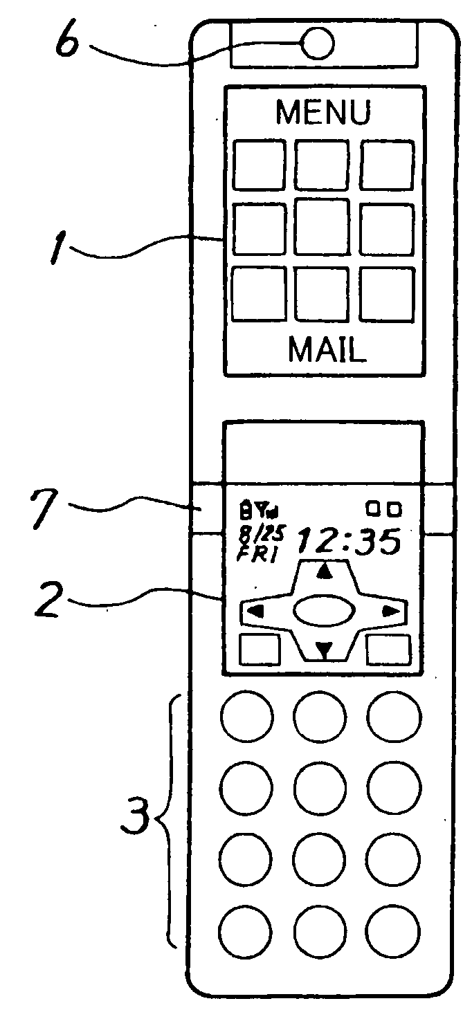
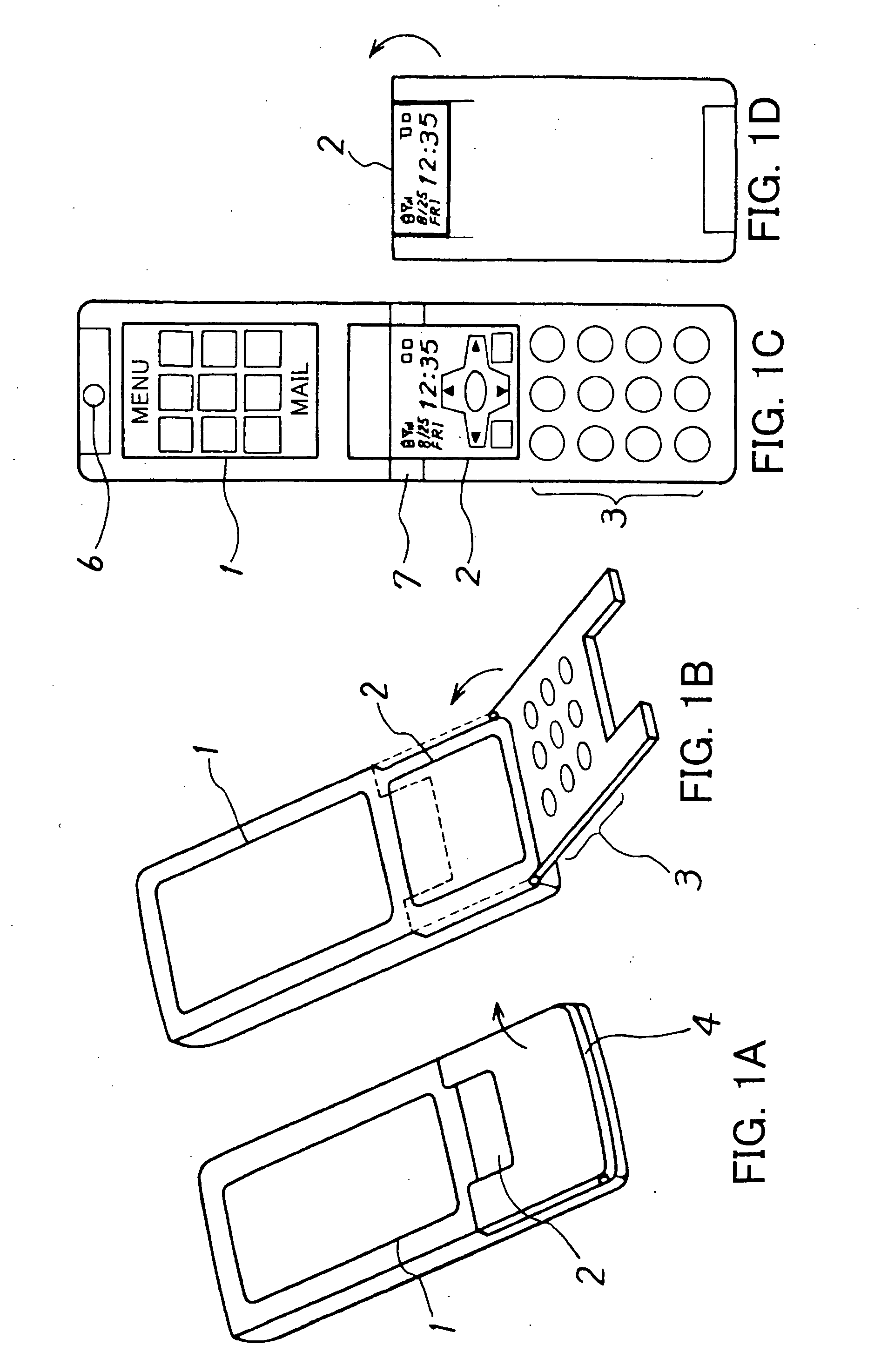
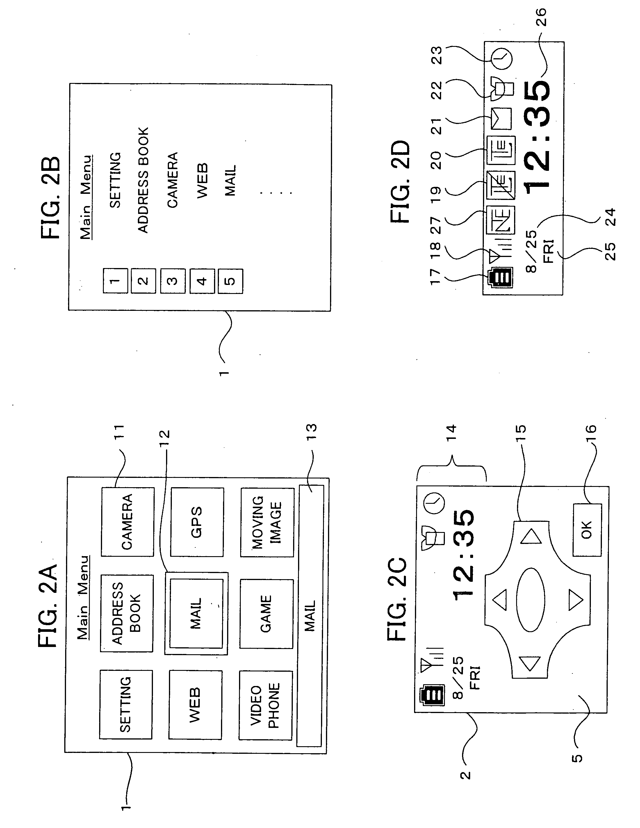
[0026]FIGS. 1A to 1D are outside views of portable telephones (including PHS) in an embodiment of the present invention; FIG. 1A and FIG. 1B illustrate a flip-type portable telephone; and FIGS. 1C and 1D illustrate a folding-type portable telephone. FIG. 1A illustrates the flip-type portable telephone when a flip 4 is in a closed state. In this state, a main screen 1 and a portion of a sub-screen 2 can be visually recognized. On the main screen 1, a menu for operating the portable telephone is displayed, and contents corre...


PUM


Abstract

A terminal apparatus is provided that has a first and a second display units; and a control unit which controls display contents of the first and the second display units respectively. The control unit displays, on the second display unit, status information as well as an operation key associated with the display contents displayed on the first display unit. The control unit changes the display contents displayed on the first display unit in response to an input with the operation key.

Description

BACKGROUND OF THE INVENTION [0001] 1. Field of the Invention [0002] The present invention relates to a terminal apparatus which has at least two (2) display units. [0003] 2. Description of the Related Art [0004] Currently, for a portable telephone (including PHS (Personal Handyphone System)), a display unit such as a liquid-crystal screen is indispensable. This is because it acts as an interface when a user conducts various operations, such as making a telephone call (including videophone), reading a schedule book or an address book to check details, calling a menu for various settings, reading and writing a mail, browsing Web contents, viewing still images and moving images and others. Considering visibility and usability, it is desirable to use the display unit as broadly as possible for above-mentioned operations. [0005] But, on the conventional display unit of the portable telephone, so-called status information such as a remaining level of a battery, an radio wave receiving con...

Claims


Application Information

Patent Timeline
Patent Type & Authority Applications(United States)
IPC IPC(8): H04M1/02H04M1/72439G06F3/14G09G5/00H04M1/23H04M1/72403H04M1/7243H04M1/72445H04M1/72469
CPCG06F3/1423H04M1/72522H04M1/72547H04M2250/52H04M1/72561H04M1/72583H04M2250/16H04M1/72555H04M1/72439H04M1/7243H04M1/72445H04M1/72469H04M1/72403
Inventor MATSUNAGA, KEIGOYAMAZAKI, TAKAHIROIZUMI, KENICHI
Owner FUJITSU LTD
Learn More