DC converters having buck or boost configurations

a technology of buck or boost configuration and converter, which is applied in the field of dc conversion, can solve the problems of loss of efficiency at high switching frequency, complex control circuit, and difficult integration of components in the integrated circuit form of the control circuit,

Inactive Publication Date: 2005-07-07
POWER INTEGRATIONS INC
View PDF3 Cites 73 Cited by
  • Summary
  • Abstract
  • Description
  • Claims
  • Application Information

AI Technical Summary

Benefits of technology

[0022] In this aspect of the invention, preferably the diode or second switch comprises a MOSFET having a source coupled to the input voltage and a drain coupled to the first winding. The f

Problems solved by technology

One of these obstacles is, typically, a need to drive the gate of one of the MOSFET switches of the converter at a voltage level above that of the converter input voltage.
Another of these obstacles is a need to power a control circuit of the converter from the input voltage in order to start up the converter.
This adds complexity to the control circuit, with a need for high voltage components to withstand the relatively (compared to the output voltage) high input voltage.
Such components are not easy to incorporate in an integrated circuit form of

Method used


Image

  • DC converters having buck or boost configurations
  • DC converters having buck or boost configurations
  • DC converters having buck or boost configurations

Examples


Embodiment Construction

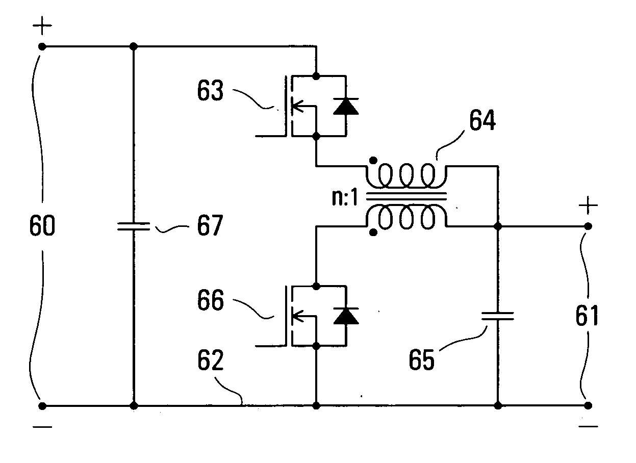
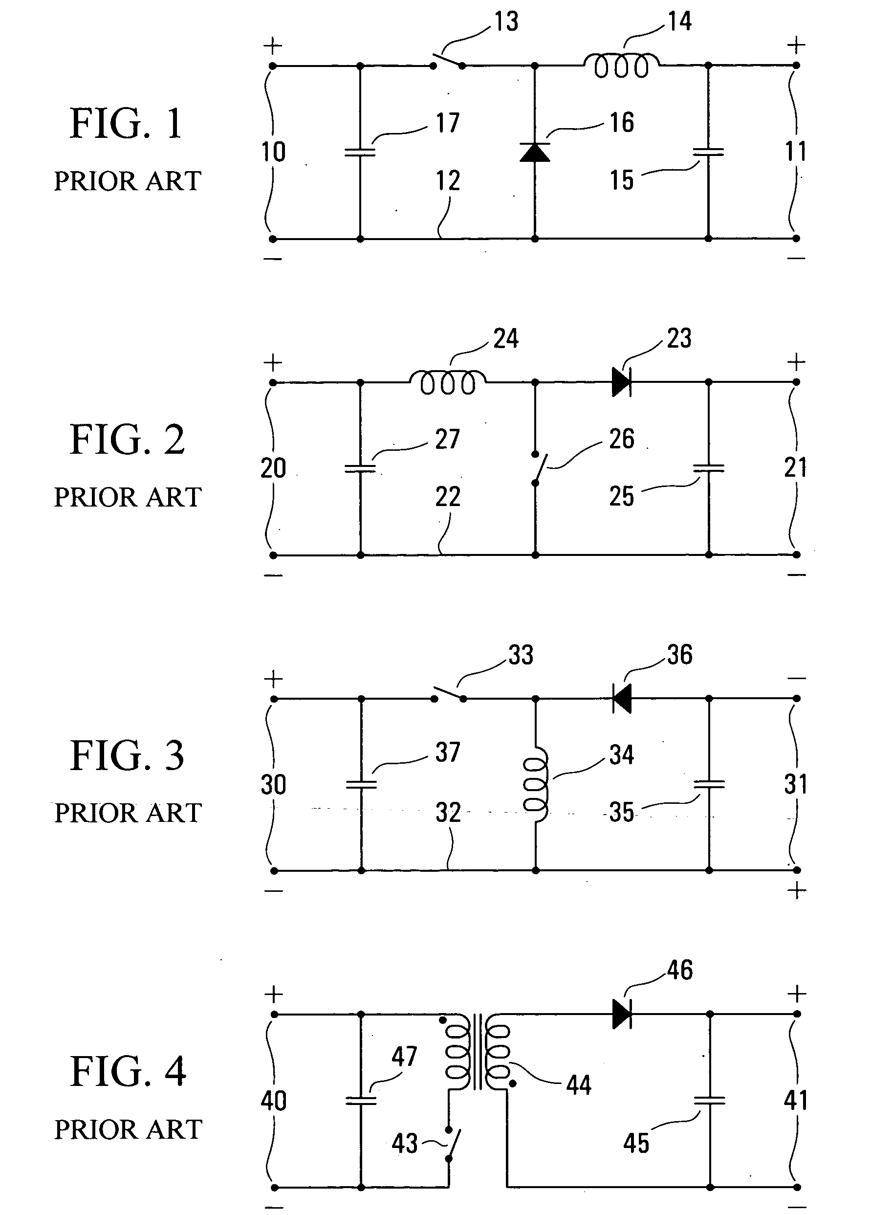
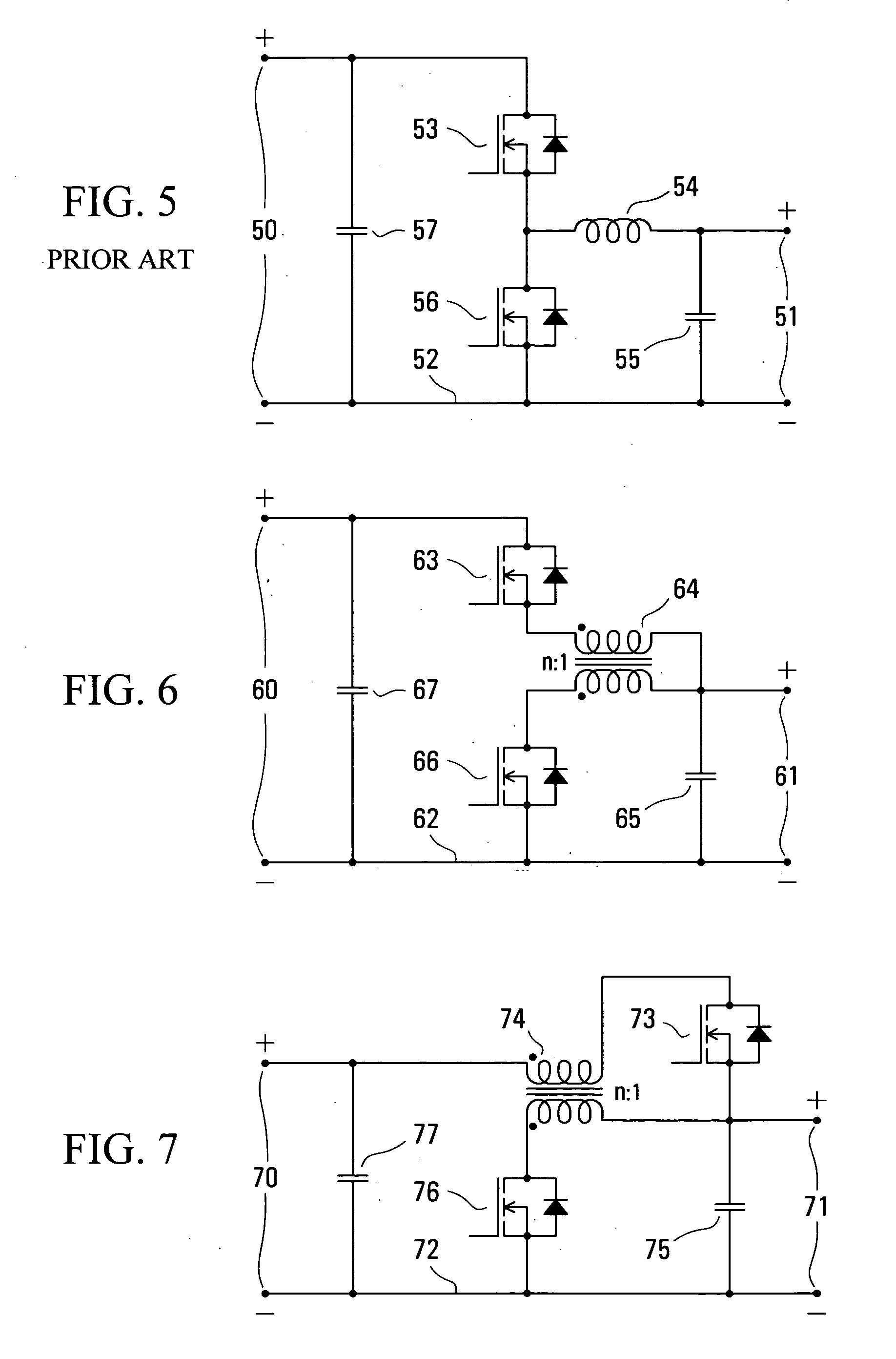
[0039] In FIGS. 1 to 7 of the drawings, various forms of regulator or DC converter are illustrated. For convenience, and to illustrate a correlation among elements of the regulators or converters, in each of these figures the elements of the converter are denoted by a two-digit reference numeral, in which the first digit corresponds to the figure number and the second digit represents a respective element of the regulator or converter.

[0040] More particularly, denoting the first digit as f to correspond to the figure number, the regulators or converters of FIGS. 1 to 7 generally (with exceptions as described below) comprise: two terminals f0 shown at the left of the respective figure; two terminals f1 shown at the right of the respective figure; a common line f2 between one of the terminals f0 and one of the terminals f1 ; a switch or diode f3 and an inductor f4 in a series path between the other of the terminals f0 and the other of the terminals f1 ; a switch or diode f6 between a...


PUM


Abstract

An inductor in a series path of a DC converter having a buck or boost configuration is constituted by a transformer with windings in series with switches of the converter. A transformer turns ratio facilitates matching switch voltage and current stresses to characteristics of MOSFETs forming the switches. A high side MOSFET can have its source at a constant voltage to facilitate driving this switch. One switch can be replaced by a diode. A transformer leakage energy removal circuit can provide an auxiliary output voltage, greater than the input voltage for a buck configuration.

Description

[0001] This invention relates to DC converters having buck or boost configurations. DC converters are also referred to as. DC-to-DC converters, DC or DC-to-DC regulators, switch mode regulators, converters, power converters, or power supplies, etc.; the term “DC converter” or simply “converter” is used primarily herein to include all such terms. [0002] These terms as used herein also embrace converters for which a supply coupled to the input circuit can comprise a relatively low frequency alternating or varying voltage optionally with a DC component, and / or for which the output can comprise a relatively low frequency alternating or varying voltage optionally with a DC component (e.g. a telephone ringing signal), in other words a DC converter that can operate in all quadrants. BACKGROUND [0003] There is a wide variety of known DC converter topologies or configurations which are derived from at least one buck regulator and / or at least one boost regulator, with or without a transformer...

Claims


Application Information

Patent Timeline
IPC IPC(8): G05F1/10H02M3/158
CPCH02M3/1582
Inventor ORR, RAY
Owner POWER INTEGRATIONS INC
Why Eureka
Try Eureka