Printable electromechanical input means and an electronic device including such input means

a technology of electromechanical input and electronic device, which is applied in the association of printed circuit non-printed electric components, static indicating devices, instruments, etc., can solve the problems of large number of separate components, large number of possible alternative ways of coupling resistive layers to reading electronics, and use of continuous electrodes along the whole length of sides of resistive layers

Active Publication Date: 2005-07-07
RPX CORP
View PDF5 Cites 37 Cited by
  • Summary
  • Abstract
  • Description
  • Claims
  • Application Information

AI Technical Summary

Benefits of technology

[0009] It is an objective of the present invention to present an structure for electromechanical input means that is simple and only requires a small number of different parts and manufacturing steps. An additional objective of the invention is to provide a structure of the above-mentioned kind that is widely adaptable for use in different kinds of electromechanical input means. A further objective of the invention is to present a method for manufacturing structurally simple electromechanical input means, particularly for portable electronic devices. A yet further objective of the invention is to present an overall structural solution for a portable electronic device that includes electromechanical input means of the kind mentioned above.

Problems solved by technology

Using continuous electrodes along the whole length of sides of the resistive layers is not the only possible alternative for coupling the resistive layers to reading electronics.
The drawbacks of prior art key pads and touch pads are mainly related to the relatively large number of separate components and / or method steps required in their manufacture.

Method used


Image

  • Printable electromechanical input means and an electronic device including such input means
  • Printable electromechanical input means and an electronic device including such input means
  • Printable electromechanical input means and an electronic device including such input means

Examples


Embodiment Construction

[0051] The exemplary embodiments of the invention presented in this patent application are not to be interpreted to pose limitations to the applicability of the appended claims. The verb “to comprise” is used in this patent application as an open limitation that does not exclude the existence of also unrecited features. The features recited in depending claims are mutually freely combinable unless otherwise explicitly stated.

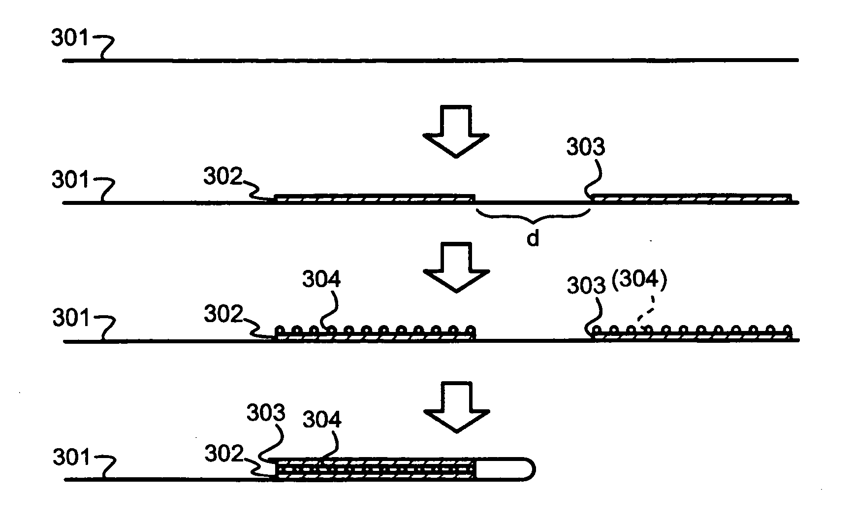
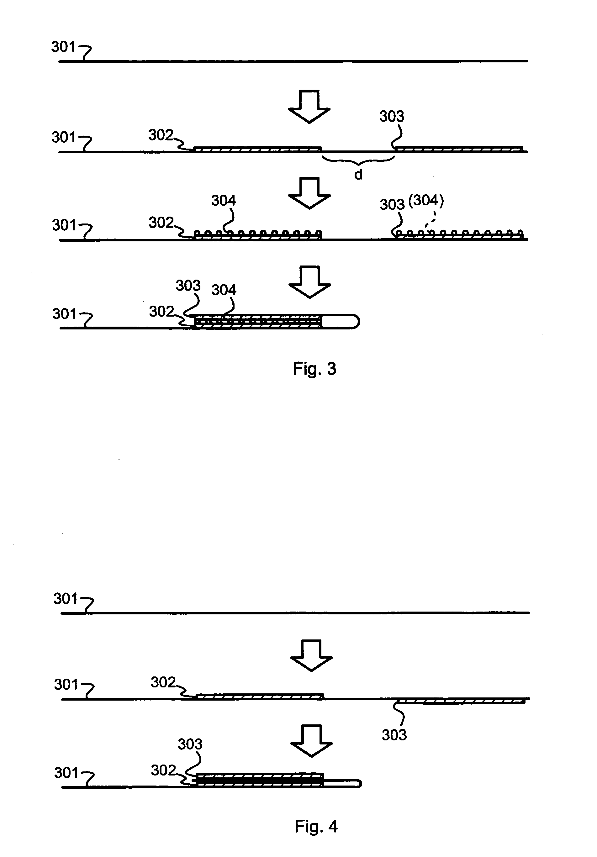
[0052]FIG. 3 illustrates schematically how certain electromechanical input means according to an embodiment of the invention are manufactured. First there is a flex 301, which at this stage may already comprise a number of conductive patterns, vias, and attached components (these are not shown for graphical clarity). A first layer 302 and a second layer 303, which both are conductive or resistive, are produced onto one surface of the flex 301 relatively close to each other. The distance d between the first and second layers 302 and 303 is long enough to allow b...


PUM


Abstract

Electromechanical input means for a portable electronic device comprise first and second layers of conductive or resistive material. The second layer overlaps the first layer at least partly so that the overlapping parts of the first and second layers together are responsive to touching or pressing to produce an electric input signal to the portable electronic device. There is a dielectric support layer for the first and second layers. At least a part of the dielectric support layer for the first layer continues past the first layer and is bent back to act as the dielectric support layer for the second layer.

Description

TECHNICAL FIELD [0001] The invention generally concerns the structures of electromechanical input means used to input data into compact-size electronical devices. Especially the invention concerns a novel electromechanical structure that facilitates advantageous physical implementation of touch pad and key pad type input means. BACKGROUND OF THE INVENTION [0002] Electronic devices such as computers, personal digital assistants, portable telephone devices and the like all need input means for enabling a human user to input commands and other information. The most commonly used input means comprise key pads and touch pads. Both of these involve the concept of producing an electric signal as a response to a pressing movement made by the user; the difference between the two is mainly in that a key pad only offers a relatively small number of discrete pressing points or keys to be pressed, while a touch pad is capable of differentiating between a large number of pressing locations and ca...

Claims


Application Information

Patent Timeline
Patent Type & Authority Applications(United States)
IPC IPC(8): G06F3/033G06F3/044G06F3/045G09G5/00H04M1/23H05K1/18
CPCG06F3/044G06F3/045H05K1/189H05K2201/10128H05K2201/10053H05K2201/10083H05K2201/055G06F3/0445G06F2203/04103
Inventor OSTERGARD, TONI
Owner RPX CORP
Why Eureka
Try Eureka