Rear projection type multi-projection display

a multi-projection display and projection type technology, applied in the direction of printers, pulse techniques, camera focusing arrangements, etc., can solve the problems of complicated adjustment operation and long adjustment operation time, and achieve smooth moving picture display, favorable quality, and the effect of avoiding tailing phenomenon

Inactive Publication Date: 2005-07-07
SEIKO EPSON CORP
View PDF12 Cites 24 Cited by
  • Summary
  • Abstract
  • Description
  • Claims
  • Application Information

AI Technical Summary

Benefits of technology

[0089] To the contrary, according to above the rear projection type multi-projection display, by performing writing twice or more to one unit screen information, it is possible to make a flicker inconspicuous. Further, a liquid crystal device of a so-called n-time speed driving (here, n is a natural number of 2 or more) is used and the solid-state light source is allowed to emit outside at least the first writing period of the liquid crystal device. Thus, it becomes possible to project intermittently the projection images onto the transmissive screen. For this reason, it is po

Problems solved by technology

Thus, there are problems in that since the installation of the image-capturing device is performed by a general

Method used


Image

  • Rear projection type multi-projection display
  • Rear projection type multi-projection display
  • Rear projection type multi-projection display

Examples


first exemplary embodiment

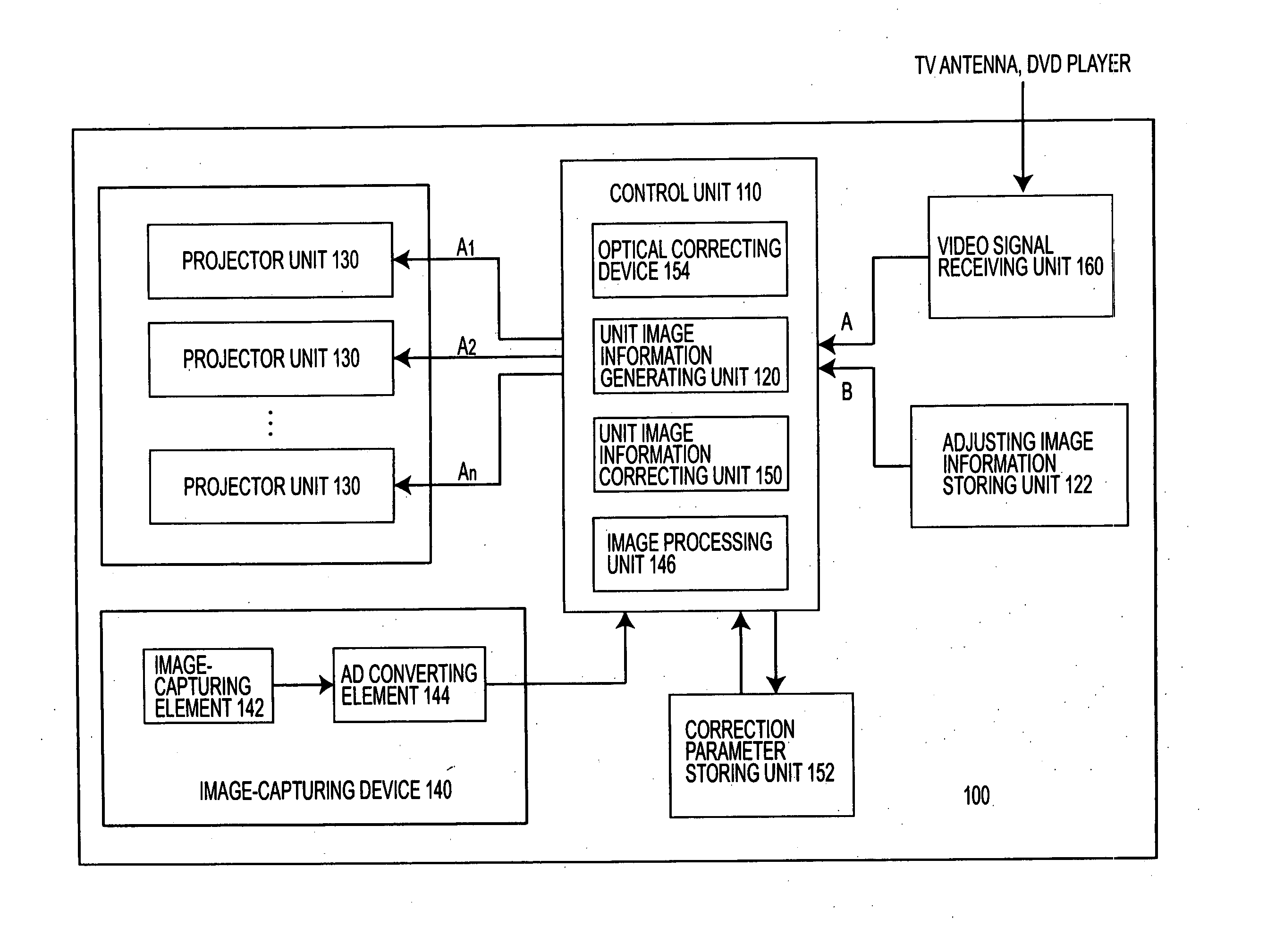
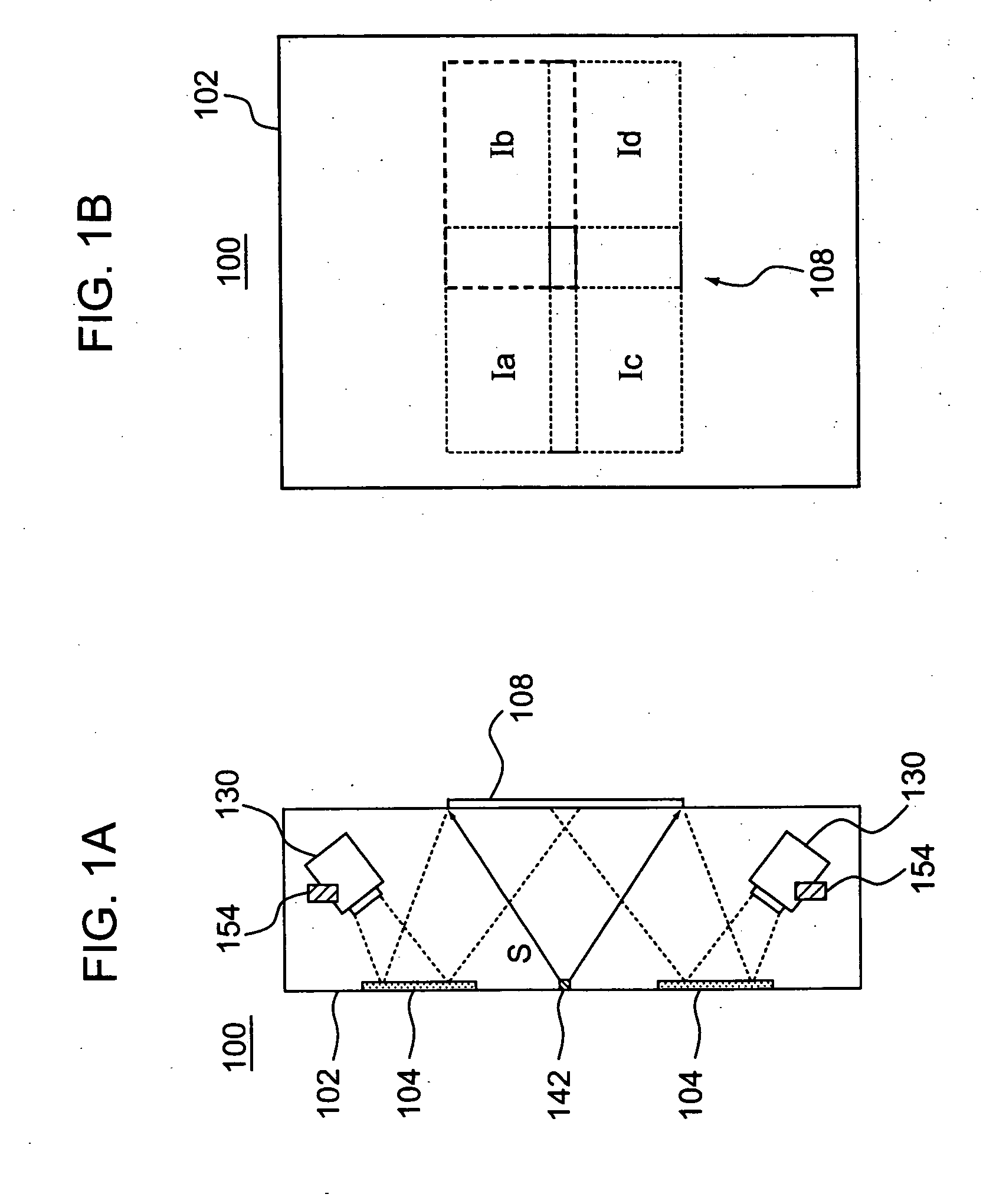
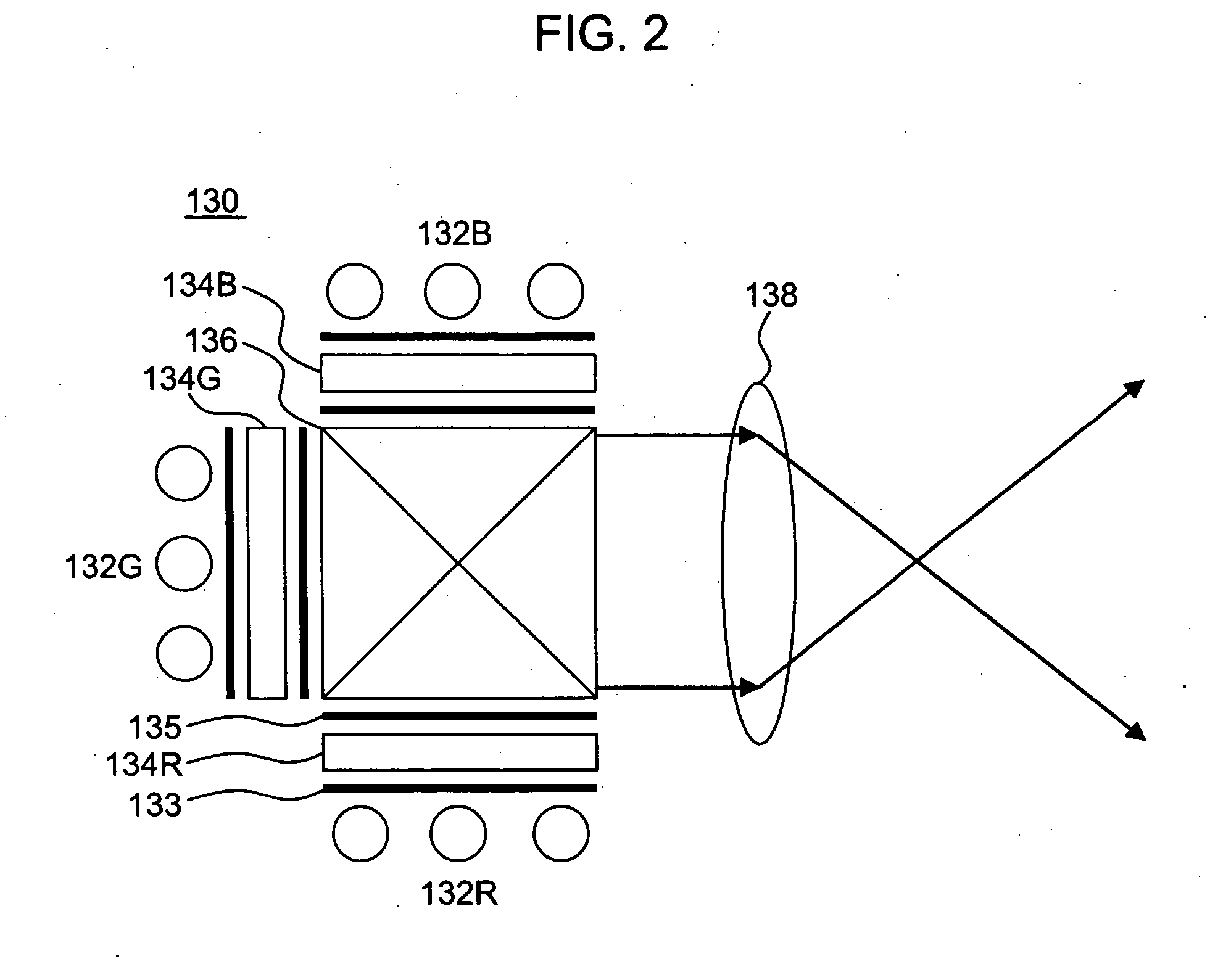
[0124] FIGS. 1A-B are schematic diagrams showing a construction of a rear projection type multi-projection display according to a first exemplary embodiment. FIG. 1A is a schematic cross-sectional view as viewed from a side and FIG. 1B is a schematic front view. FIG. 2 is a schematic diagram showing a construction of a projector unit in the rear projection type multi-projection display according to the first exemplary embodiment. FIGS. 3 to 5 are schematic block diagrams showing an outline of the rear projection type multi-projection display according to the first exemplary embodiment.

[0125] In the rear projection type multi-projection display 100 according to the first exemplary embodiment, projection images from four projector units 130 (in FIG. 1A, only two projector units are shown) which are arranged in a housing 102 are reflected by reflectors 104 to be projected onto a transmissive screen 108, as shown in FIGS. 1A-B. As shown in FIG. 2, the respective projector units 130 inc...

second exemplary embodiment

[0183] FIGS. 14A-B are schematic diagrams showing a construction of a rear projection type multi-projection display according to a second exemplary embodiment. FIG. 15 is a schematic diagram illustrating advantages of the rear projection type multi-projection display according to the second exemplary embodiment.

[0184] The rear projection type multi-projection display 200 according to the rear projection type second exemplary embodiment is constructed such that an optical axis of a projection light flux from each of the projector units 130 is orthogonal to the screen surface of the transmissive screen 208, as shown in FIGS. 14A-B.

[0185] For this reason, the unit images from the respective projector units 130 do not have trapezoidal distortion. As a result, advantages in the rear projection type multi-projection display 200 according to the second exemplary embodiment are as shown in FIG. 15, unlike FIG. 6 showing advantages in the rear projection type multi-projection display 100 a...

third exemplary embodiment

[0187]FIG. 16 is a schematic block diagram showing an outline of a rear projection type multi-projection display according to the third exemplary embodiment. FIGS. 17A-B are schematic diagrams illustrating advantages of the rear projection type multi-projection display according to the third exemplary embodiment. FIG. 17A is a diagram showing advantages in the case in which the unit image has trapezoidal distortion, and FIG. 17B is a diagram showing advantages in the case in which the unit image does not have trapezoidal distortion.

[0188] As shown in FIG. 16, the rear projection type multi-projection display 300 according to the third exemplary embodiment has a construction of a control unit different from the rear projection type multi-projection display 100 according to the first exemplary embodiment. That is, in the rear projection type multi-projection display 300 according to the third exemplary embodiment, the control unit 112 has a construction excluding the optical correcti...


PUM


Abstract

Exemplary embodiments of the invention provide a circuit that includes a plurality of projector units to modulate and project light from a light source based on image information, a transmissive screen to which projection images from the plurality of projector units are projected, an image-capturing device disposed in a housing to capture predetermined regions of the projection images projected onto the transmissive screen, a unit image information generating unit to generate image information to be inputted to each of the plurality of projector units, and a unit image information correcting unit to correct the unit image information based on a result captured by the image-capturing device. Therefore, it is possible to perform easily the adjustment process and to further reduce the adjustment time.

Description

BACKGROUND OF THE INVENTION [0001] 1. Field of Invention [0002] The present invention relates to a rear projection type multi-projection display. [0003] 2. Description of Related Art [0004] Related art documents Japanese Unexamined Patent Application Publication No. 8-82854, Japanese Unexamined Patent Application Publication No. 8-94974, Japanese Unexamined Patent Application Publication No. 2001-339672, International Publication Pamphlet No. 99 / 31877, Japanese Unexamined Patent Application Publication No. 9-326981, Unexamined Patent Application Publication No. 2001-251651, Japanese Unexamined Patent Application Publication No. 6-178327, Japanese Unexamined Patent Application Publication No. 9-211386, U.S. Pat. No. 5,956,000, disclose a rear projection type multi-projection display in which a plurality of projector units (projection optical unit) are arranged in a horizontal direction and in a vertical direction and projection images from the plurality of projector units are project...

Claims


Application Information

Patent Timeline
IPC IPC(8): H04N3/22H04N5/74H04N9/31
CPCH04N5/74H04N9/3197H04N9/3147
Inventor MIYAZAWA, YASUNAGAHASEGAWA, HIROSHI
Owner SEIKO EPSON CORP
Why Eureka
Try Eureka