Side-emitting led marine signaling device

a signaling device and led marine technology, applied in the field of side-emitting led marine signaling devices, can solve the problems of complex three-piece mold manufacturing, incandescent lamps with relatively short service life, and generally relatively tall lens of incandescent lamps, so as to achieve the effect of reducing maintenance and power consumption

Inactive Publication Date: 2005-07-07
TIDELAND SIGNAL
View PDF68 Cites 30 Cited by
  • Summary
  • Abstract
  • Description
  • Claims
  • Application Information

AI Technical Summary

Benefits of technology

[0008] It is, therefore, an object of the present invention to provide a signaling device that uses LEDs to minimize maintenance and power consumption.

Problems solved by technology

Fresnel lenses for incandescent lamps are generally relatively tall and require complex three-piece molds for manufacturing.
Incandescent lamps have a relatively short service lifetime and thus require significant maintenance.
Incandescent lamps also consume a great amount of power and generate a great deal of heat.
Producing a sufficiently bright and uniform beam of omni-directional illumination has been difficult to achieve using forward-directed LEDs.
However, McDermott suffers the disadvantage that such grouped LEDs require a Fresnel optic to optimize the light emerging from the device, and such Fresnel lenses require complex, expensively manufactured three-piece molds.
The unit, however, also suffers the disadvantage of lacking an optical system to transmit light efficiently, and, instead, employs a transparent cover that does not, without modification, function to further improve the visibility of the device.
However, Cha suffers the disadvantage that the cover consists of a complex lens cover with a plurality of focusing lenses on the interior of the cover.
Such a lens is complicated and expensive to manufacture.
Furthermore, m a single-optical element, such as described in Cha, manufacturing constraints limit the refractive power available using common lenses.
The limited refractive power thus limits the focusing power of the lens, as well as effective transmittance along the plane of the horizon.

Method used


Image

  • Side-emitting led marine signaling device
  • Side-emitting led marine signaling device
  • Side-emitting led marine signaling device

Examples


Embodiment Construction

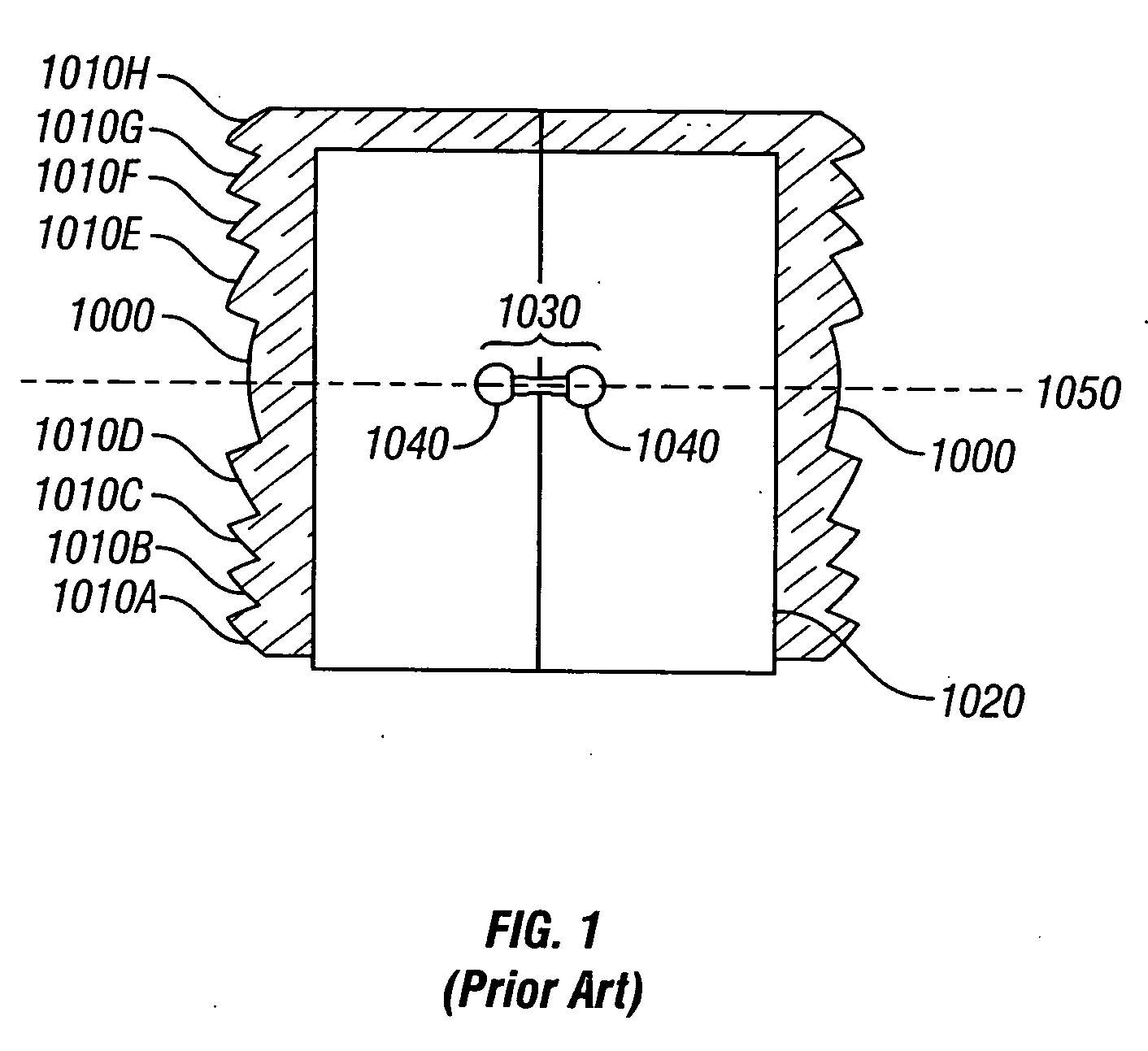
[0036] Referring to FIG. 1, a cross sectional view shows a bent focal line lighting device conventionally used. The bent focal line lighting device shown in FIG. 1 is typically used in marine applications as a navigational beacon and is described in U.S. Pat. No. 6,048,083 to McDermott. As shown in FIG. 1, a contoured optic creates a plurality of focal points to intensify the light created by a plurality of LEDs. The lighting device includes a lens with a central exterior lens surface 1000 and optical steps 1010A though 1010H, and an interior lens surface 1020. The central exterior lens surface 1000 and the optical steps 1010A through 1010H represent a typical Fresnel lens contour, substituted for a single curved exterior lens surface. The lighting device includes a lamp assembly 1030 composed of a plurality of LED devices 1040 located inward of the interior lens surface 1020. Light is emitted from the LED devices 1040 of the lamp assembly 1030, and is refracted according to the bas...


PUM


Abstract

The present invention is directed to a signaling device that incorporates a side-emitting light emitting diode (LED), a first optic, which partially deviates and focuses the radiated light, and a second optic, which centers the beam on the horizon and determines the final vertical divergence. The means for powering the device is either a self-contained photovoltaic system or an external battery supply. The means for controlling the device is electronic circuitry.

Description

BACKGROUND OF THE INVENTION [0001] The present invention relates generally to signaling devices, and particularly to signaling devices used in marine navigation applications. Signaling devices, particularly in marine applications, are used to warn or alert vessels of various conditions, structures or the like and to otherwise serve as navigational aides. Generally, signaling devices emit light in an omni-directional manner in order to adequately signal those approaching the signaling device from any direction. Signaling lights must generate an intense beam that is substantially uniform over a wide field of illumination, especially along the horizon. For a useable marine light that is highly visible in all directions, it is necessary to manipulate emitted light to center the beam on the horizon. [0002] Signaling devices in the past have used incandescent lamps to illuminate a broad field. Omni-directional signal lights employing incandescent lamps require lenses with very large verti...

Claims


Application Information

Patent Timeline
Patent Type & Authority Applications(United States)
IPC IPC(8): F21S8/00F21S9/02F21S9/03F21V5/04
CPCF21S9/02F21S9/037F21W2111/04F21W2111/00F21Y2101/02F21V5/046F21Y2115/10
Inventor KLEIN, W. RICHARD
Owner TIDELAND SIGNAL
Why Eureka
Try Eureka