Communication node and packet transfer method

a packet transfer and communication node technology, applied in data switching networks, two-way working systems, frequency-division multiplexes, etc., can solve the problems of reducing system throughput and increasing the demand for radio communications

Inactive Publication Date: 2005-07-07
KK TOSHIBA
View PDF16 Cites 40 Cited by
  • Summary
  • Abstract
  • Description
  • Claims
  • Application Information

AI Technical Summary

Benefits of technology

[0012] In view of the situations set forth above, an object of the present invention is to provide a communication node and a packet transfer method which can reliably transfer a packet with a payload including data having error resistance in radio environments.
[0026] With the above features, since the header portion of a packet, for example, generally does not have error resistance, the header portion can be given a strong error correction ability. It is therefore possible to reduce a probability of the occurrence of errors in the packet header portion during radio transmission, and to avoid the packet from being discarded in a packet header processing unit in the communication node.

Problems solved by technology

Recently, demand for radio communications has experienced an explosive increase.
However, the following problem arises in realizing such Internet multimedia communication.
This is problematic because the packet is unnecessarily discarded if the payload can recover lost data, resulting in reduced system throughput.

Method used


Image

  • Communication node and packet transfer method
  • Communication node and packet transfer method
  • Communication node and packet transfer method

Examples


first embodiment

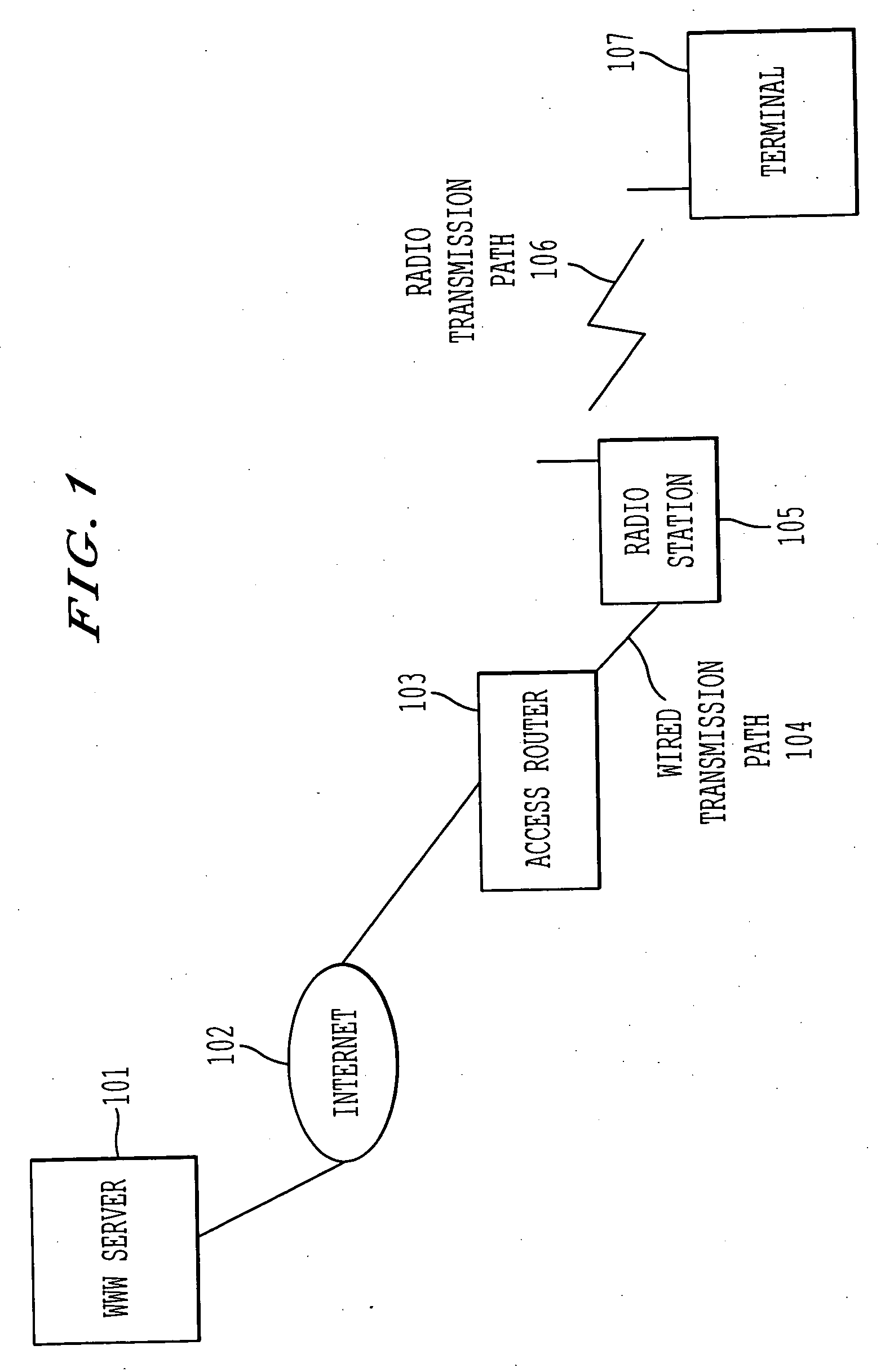
[0052]FIG. 1 shows one example of an overall configuration of a network system according to the present invention.

[0053] Referring to FIG. 1, a terminal 107 communicates with a WWW server 101 via a radio transmission path 106, such as a radio public network. Here, the WWW server 101, an access router 103, and the terminal 107 are nodes that are connected to the Internet 102.

[0054] In the Internet communication system shown in FIG. 1, transmission paths between the access router 103 and the terminal 107 (i.e., a wired transmission path 104 and the radio transmission path 106) are considered part of the Internet 102, beyond just the wired network. However, for purposes of explanation, the transmission paths 104 and 105 are considered separate from the Internet 102 to highlight the present invention, which focuses on the differences in transmission properties (e.g., a transmission error) between those transmission paths 104 and 105 and the Internet 102.

[0055] The terminal 107 securel...

second embodiment

[0121]FIG. 14 shows one example of an entire sequence of the negotiation between the access router 103 and the terminal 107 according to the

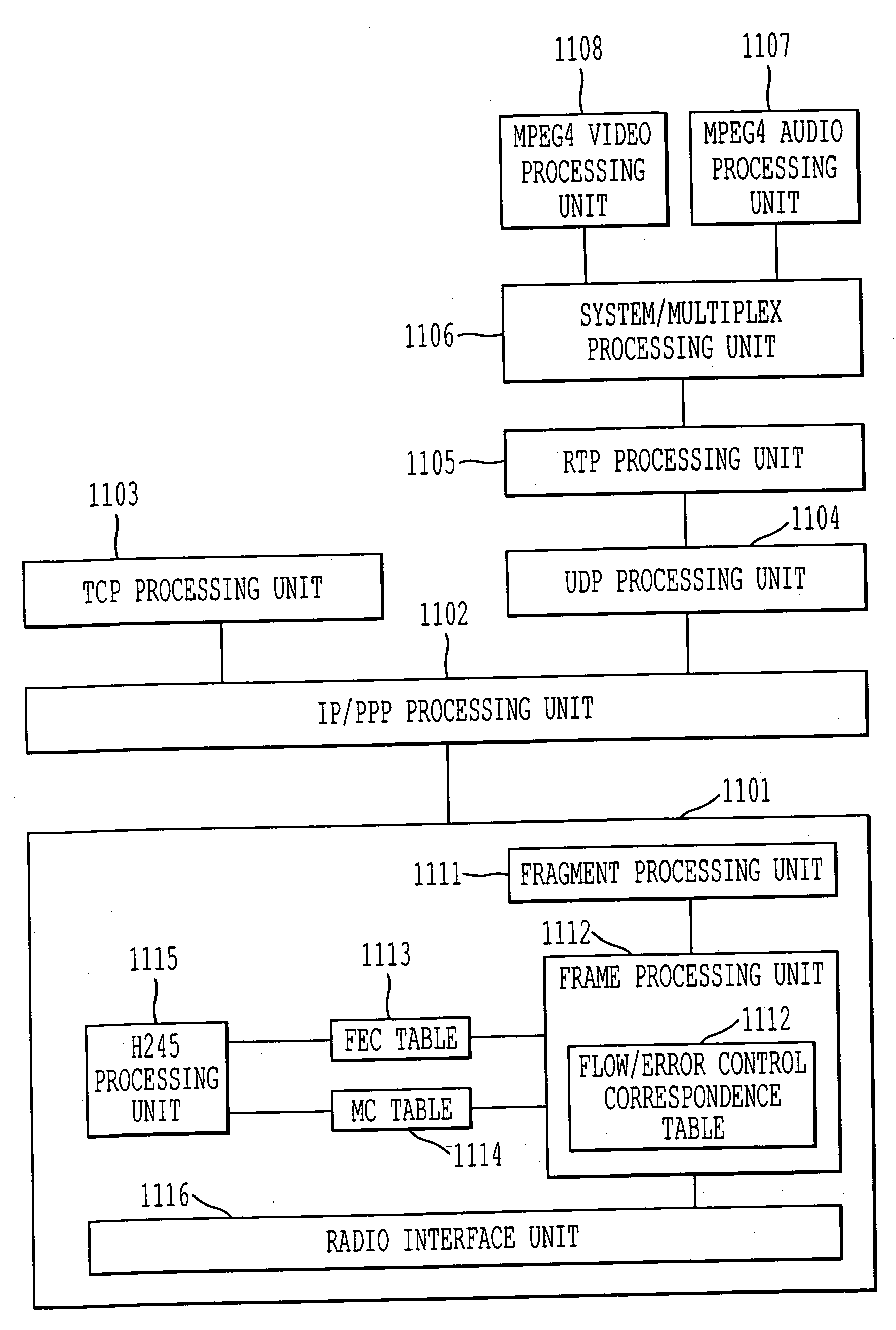
[0122] In the first embodiment, as shown in FIG. 6, the type of FEC to be used and other information regarding data are negotiated using separate codes (i.e, the FEC code and the MC code). In this second embodiment, the FEC code is not used, and the value of the MC code, including the type of FEC to be used, is decided during the H.245 negotiation (i.e., what the value of the MC code means is decided through the negotiation). In other words, the negotiation is performed such that both the transmitting and receiving sides can recognize the type of FEC to be used from the MC value. Results of the negotiation are reflected in the MC table shown in, by way of example, in FIG. 15. The MC table is held in both nodes, i.e., the access router 103 and the terminal 107.

[0123] It is negotiated, for example, that in the case of MC=1 and MC=2, data that hav...


PUM


Abstract

A communication node which can reliably transfer a packet with a payload including data having error resistance in radio environments is disclosed. A packet to be transmitted is divided into segments to form a plurality of packet segments. From among a plurality of error correction schemes that have been prepared in advance, the scheme to be employed is selected for each of the packet segments in accordance with predetermined criteria, and the selected error correction scheme is applied to each packet segment. Subsequently, the processed packet segment is transmitted to the network. Packet segments are received from the network. From among a plurality of error correction schemes prepared in advance, the scheme to be employed is selected for each of the received packet segments based on predetermined information contained in each received packet segment, and the selected error correction scheme is applied to the received packet segment. An original packet is formed from the plurality of processed packet segments.

Description

CROSS REFERENCE TO RELATED APPLICATION [0001] This application claims benefit of priority to Japanese Patent Application No. P10-249859 filed Sep. 3, 1998, the entire disclosure of which is incorporated by reference herein. BACKGROUND OF THE INVENTION [0002] 1. Field of the Invention [0003] The present invention relates to a communication node and a packet transfer method for transferring a segmented packet, and more particularly to a communication node and a packet transfer method for transferring a packet over a radio network which is a part of global packet-switched network (e.g., Internet). [0004] 2. Description of the Background [0005] Recently, demand for radio communications has experienced an explosive increase. An infrastructure for radio communications, represented by cellular phones and PHS (Personal Handy Phone system), has been constructed at a drastically increased pace in recent years. Not only has voice communications been the focus of attention, data communications ...

Claims


Application Information

Patent Timeline
Patent Type & Authority Applications(United States)
IPC IPC(8): H04L1/00H04L12/28H04L12/70H04L29/06H04N7/173H04N19/00H04N19/65H04N21/2383H04N21/24
CPCH04L1/007H04L1/0072H04L29/06027H04L69/161H04L69/16H04L69/22H04L65/607H04L65/70H04L65/1101
Inventor SAITO, TAKESHITSUNODA, KEIJIKAMAGATA, EIJIKATO, NORIYASUTOMODA, ICHIROTANAKA, HIROKAZU
Owner KK TOSHIBA
Why Eureka
Try Eureka