Gyroscopic system for boresighting equipment

a technology of gyroscopic system and boresighting equipment, which is applied in the direction of instruments, weapons, aiming means, etc., can solve the problems of limited use of telescope and target board, serious limit of ultimate accuracy, and limited method of alignment to transfer parallel lines

Active Publication Date: 2005-07-14
AIRPORTS AUTHORITY OF INDIA
View PDF34 Cites 31 Cited by
  • Summary
  • Abstract
  • Description
  • Claims
  • Application Information

AI Technical Summary

Benefits of technology

[0019] In another embodiment of the invention, a gyroscopic system for translating parallel and non-parallel lines between a reference line and a device to be aligned with respect to the reference line is provided. The system includes a first inertial sensor configured to be substantially stationary, the first inertial sensor comprising a first three-axis gyroscopic sensor configured to produce an output signal and a reflector. A second inertial sensor is configured to be portable so as to be positionable adjacent to the first inertial sensor and comprises a gimbal restricted to two physical axes, a

Problems solved by technology

The use of the telescope and target board is limited to the transfer of parallel lines to align stations.
Again, this method of alignment is limited to the transfer of parallel lines.
Both of these methods for boresight alignment have procedural and equipment aspects which seriously limit their ultimate accuracy.
Some of these limitations include: the reliance on the proper alignment of the human eye with the optical system (parallax) for error readings; the correct positioning of the target board not only in standoff position but in pitch, yaw and roll positions; the use of a finite focal length reticle as a reference; the movement of the target board during alignment on the flightline due to wind and other factors; the warping or bending of the Christmas tree; and the movement of the aircraft itself, among other limitations.
Beyond accuracy, there are two other factors which make these methodologies undesirable: the size and weight of the auxiliary equipment, and the time needed to complete a station alignment.
The station a

Method used


Image

  • Gyroscopic system for boresighting equipment
  • Gyroscopic system for boresighting equipment
  • Gyroscopic system for boresighting equipment

Examples


Embodiment Construction

[0036] Embodiments of the invention are discussed in detail below. In describing embodiments, specific terminology is employed for the sake of clarity. However, the invention is not intended to be limited to the specific terminology so selected. While specific exemplary embodiments are discussed, it should be understood that this is done for illustration purposes only. A person skilled in the relevant art will recognize that other components and configurations can be used without parting from the spirit and scope of the invention. All references cited herein are incorporated by reference as if each had been individually incorporated.

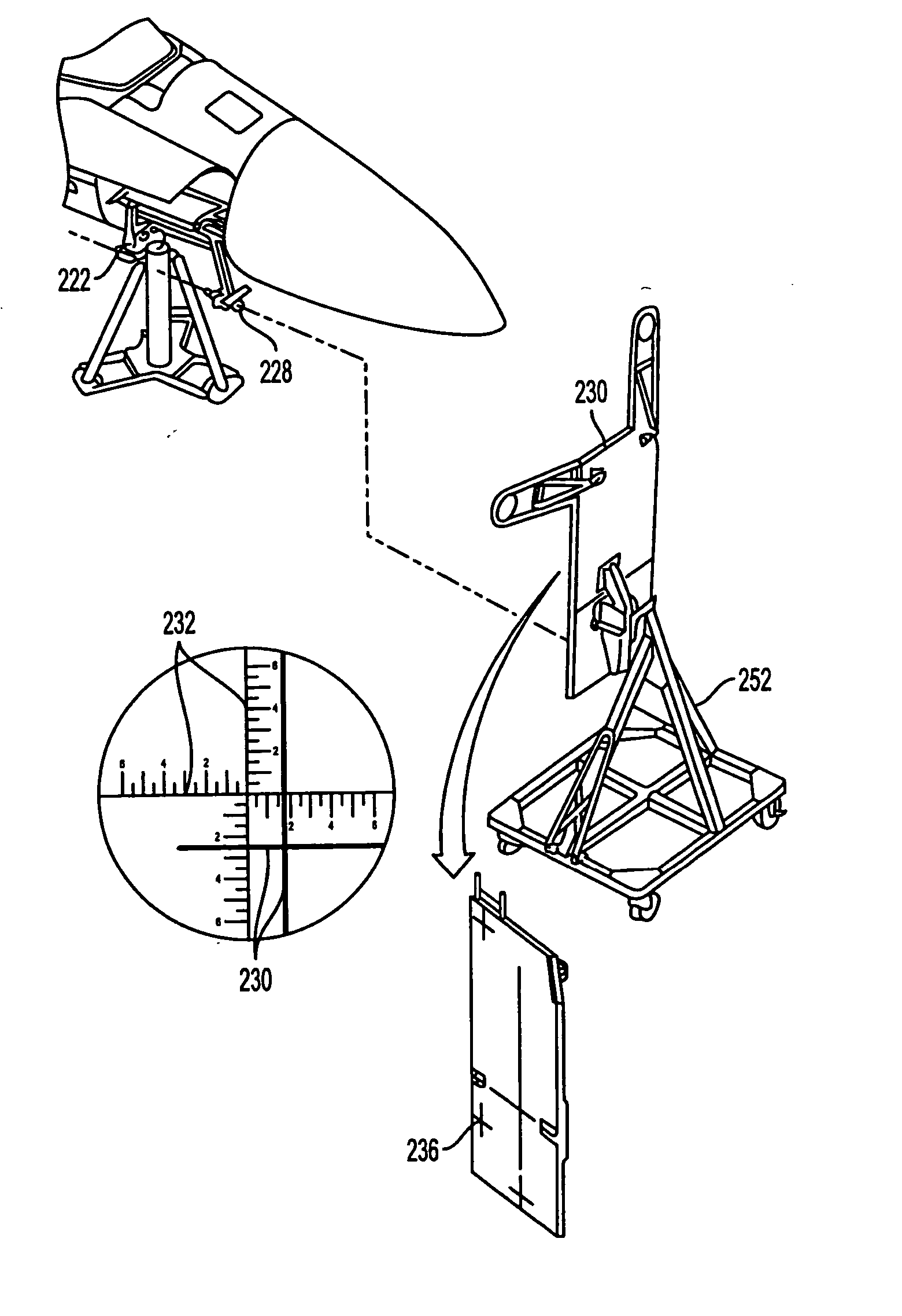
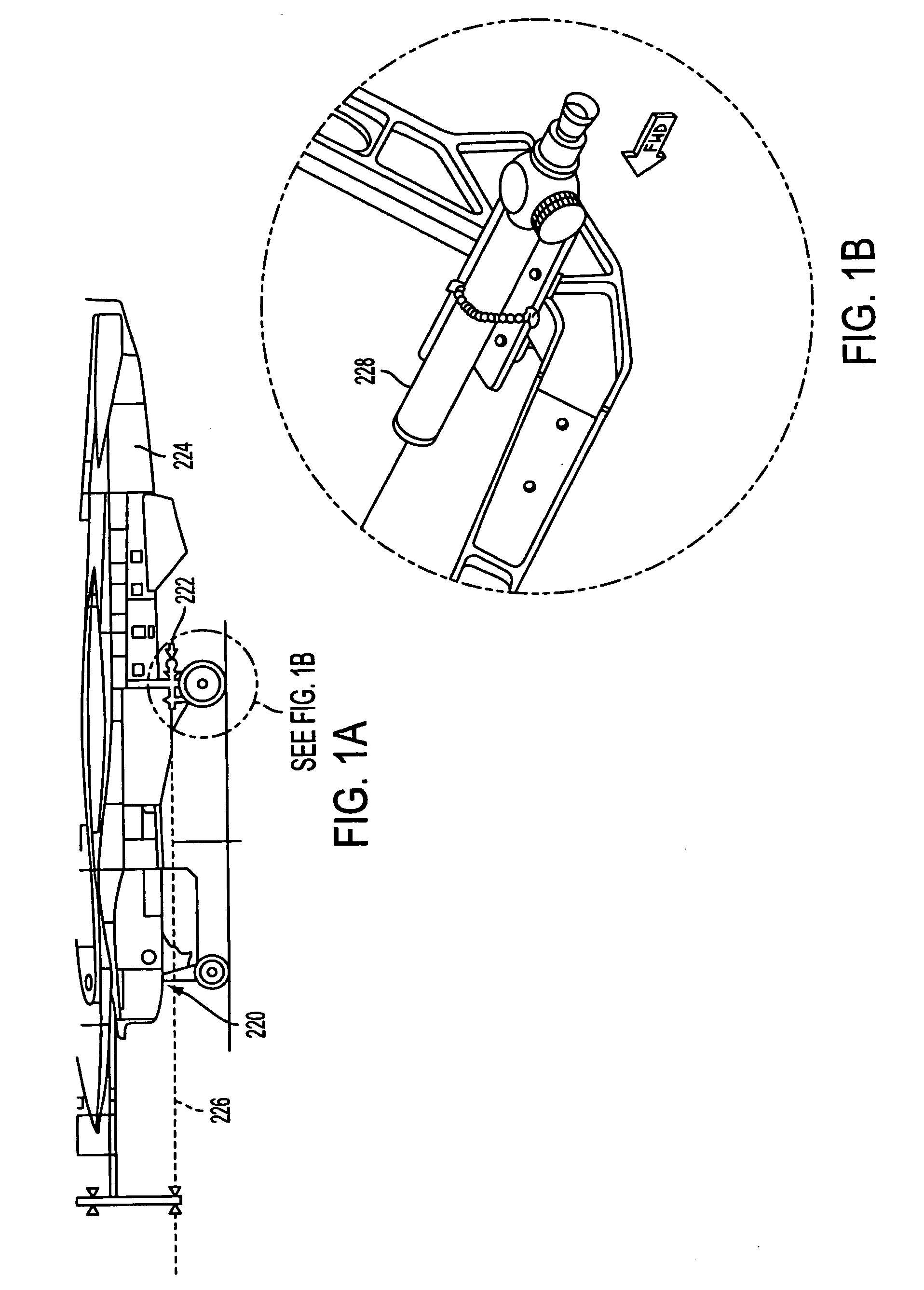
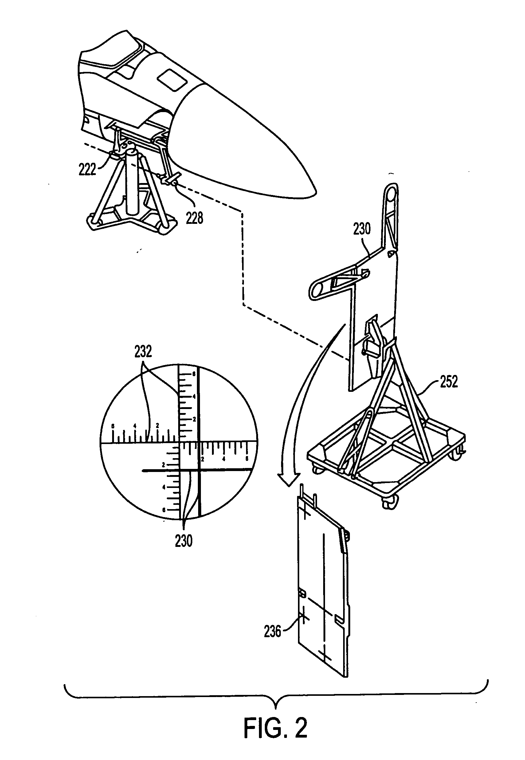
[0037] While embodiments of the invention are designed to be used for alignment on any device needing information on the relative orientation of two structural lines, two virtual lines, or one structural and one virtual line, an exemplary embodiment of the invention is described in connection with aircraft weapon and sensor station alignment for illustr...


PUM


Abstract

A gyroscopic system for translating parallel and non-parallel lines between a reference line and a device to be aligned with respect to the reference line is provided. The system includes a first inertial sensor configured to be substantially stationary, the first inertial sensor comprising a first three-axis gyroscopic sensor configured to produce an output signal and a reflector. A second inertial sensor is configured to be portable so as to be positionable adjacent to the first inertial sensor and comprises a gimbal restricted to two physical axes, a gimbal drive system, an electromagnetic energy beam generator, a second three-axis gyroscopic sensor configured to generate an output signal, and a collimator. The collimator is operable to determine an angle between a beam projected by the beam generator and a beam reflected from the reflector and to generate an output signal indicative of the determined angle. A control circuit is operable to process output signals generated by the collimator and the first and second three-axis gyroscopic sensors and determine relative orientations of the first and second inertial sensors with respect to each other.

Description

BACKGROUND OF THE INVENTION [0001] 1. Field of the Invention [0002] The present invention relates generally to a system for aligning a device using the relative orientation of two structural lines, two virtual lines, or one structural and one virtual line. The invention further relates to a method and apparatus for optically acquiring a reference line and transferring parallel or non-parallel lines to determine the orientation of a device with respect to the reference. [0003] 2. Related Art [0004] In order to control equipment such as sensors, guns, cameras and antennae mounted on vehicles such as aircraft or spacecraft, it is important to align the equipment boresights with respect to a reference axis on the vehicle. A number of methods exist for bringing weapon or navigational stations into alignment with the Armament Datum Line (ADL) on a variety of aircraft. The ADL defines the center line of the aircraft; however, it is more than simply a line because it also provides a roll re...

Claims


Application Information

Patent Timeline
IPC IPC(8): F41G3/32
CPCF41G3/326F41G3/00F41G3/32
Inventor JAKLITSCH, JAMES J.EHART, ADAM F.JONES, DOUG A.MARKEY, JAY M.LANDSBERG, GARY B.
Owner AIRPORTS AUTHORITY OF INDIA
Why Eureka
Try Eureka