Resonator with retention ribs

a technology of resonators and ribs, applied in the field of resonators, can solve the problems of lack of performance and add expense, and achieve the effect of cost-effectiveness and simple structur

Inactive Publication Date: 2005-07-14
FLEETGUARD INC
View PDF32 Cites 67 Cited by
  • Summary
  • Abstract
  • Description
  • Claims
  • Application Information

AI Technical Summary

Benefits of technology

[0003] The present invention provides a simple, cos

Problems solved by technology

Other types of structures have additional elastomer seals, adding expense.
Other

Method used


Image

  • Resonator with retention ribs
  • Resonator with retention ribs
  • Resonator with retention ribs

Examples


Embodiment Construction

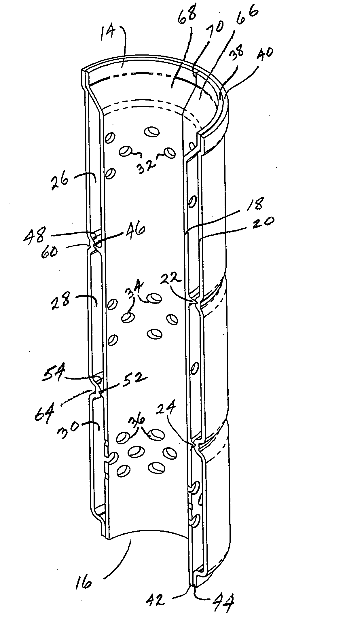
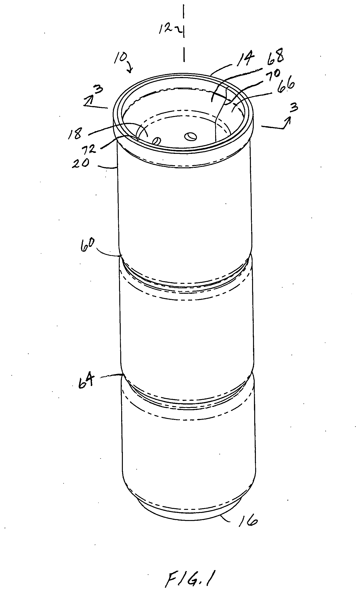
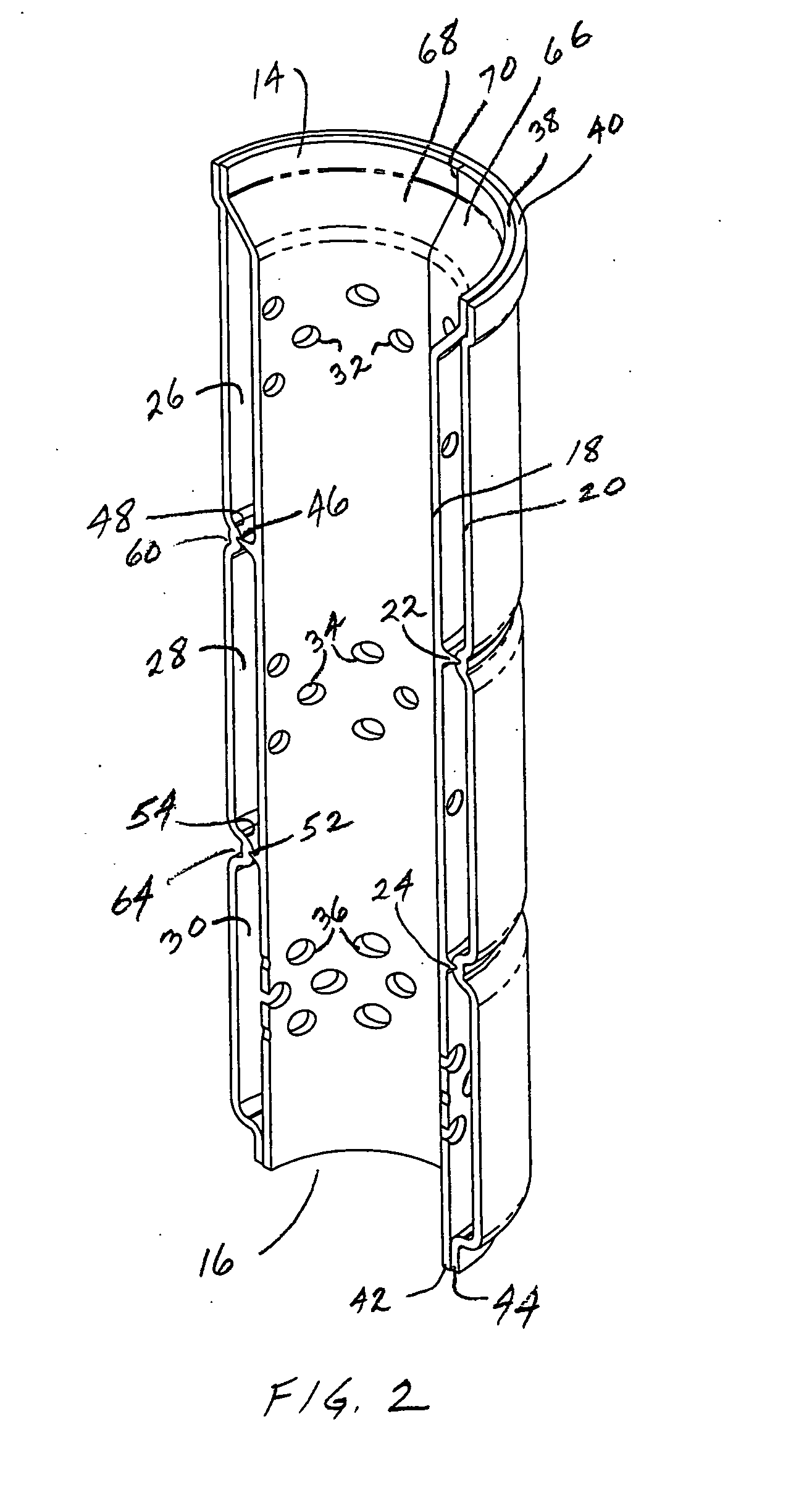
[0008]FIG. 1 shows a resonator 10 extending axially along an axis 12 between distally opposite axial ends 14 and 16 providing an inlet and an outlet, respectively, for example for receiving intake combustion air at inlet 14 and delivering the combustion air from outlet 16 to an internal combustion engine (not shown). Resonator 10 has an inner perforated tube 18, FIGS. 2-4, an outer shell 20, and at least one and preferably two or more annular ribs such as 22, 24 spaced axially between inlet 14 and outlet 16 and extending radially between inner perforated tube 18 and outer shell 20. In preferred form, inner tube 18 is an injection molded plastic member, and outer shell 20 is a blow molded or rotationally molded plastic member, and the ribs extend integrally radially outwardly from inner tube 18. The ribs define a first resonant chamber 26 between inner perforated tube 18 and outer shell 20 axially upstream of rib 22, a second resonant chamber 28 between inner perforated tube 18 and o...


PUM


Abstract

A resonator includes an inner perforated tube, an outer shell, and a plurality of annular ribs extending radially therebetween and defining resonant chambers. Progressive stepping of ribs and grooves enables axial insertion assembly with minimal cost. The need for welding or secondary bonding operations is eliminated.

Description

BACKGROUND AND SUMMARY [0001] The invention relates to resonators, including intake resonator silencers for internal combustion engines. [0002] Intake resonators are known in the art, and are constructed from various materials including metal and / or plastic. Blow molded bottle style resonators are known and fitted under the hood of automobiles, trucks, agricultural and construction vehicles, marine vehicles, and recreational vehicles. Various constructions employ hollow structures made of plastic which are bonded together using vibration or sonic welding or other types of friction welding. Other types of structures have additional elastomer seals, adding expense. Other structures of reduced cost are not gas tight, and therefore lack in performance. [0003] The present invention provides a simple, cost effective resonator without performance trade-off.BRIEF DESCRIPTION OF THE DRAWING [0004]FIG. 1 is a perspective assembly view of a resonator in accordance with the invention. [0005]FIG...

Claims


Application Information

Patent Timeline
IPC IPC(8): F01N1/02F01N1/08F02B27/02F02M35/104F02M35/12
CPCF01N1/02F02M35/1266F02M35/1216
Inventor KNIGHT, JESSIE A.CONNOR, MICHAEL J.
Owner FLEETGUARD INC
Why Eureka
Try Eureka