
Structure and method for the affixing of a pretensioner gas generator

Active Publication Date: 2005-07-14
SANOH IND CO LTD
View PDF7 Cites 16 Cited by
  • Summary
  • Abstract
  • Description
  • Claims
  • Application Information

AI Technical Summary

Benefits of technology

[0010] Thereupon, an object of the present invention is to improve the function of the pretensioner without the need to use an additional component part or to increase the thickness of the wall of the pipe, that is to say, an object of the present invention is to provide a structure and method for the affixing of a pretensioner gas generator by which gas generators containing an increased quantity of explosive can be more securely held.
[0015] According to the structure for the affixing of the pretensioner gas generator of the abovementioned claim 1, because an annular rib that projects outward in the axial direction is formed in the inner circumferential edge part of the calked part, the strength of the calked part is increased by the presence of the annular rib wherein, accordingly, without the need to use an additional component part or to increase the thickness of the wall of the pipe, a gas generator containing an increased quantity of explosive can be more securely held.
[0016] In addition, according to the structure for the affixing of the pretensioner gas generator of the abovementioned claim 2, because the diameter of the abovementioned annular rib is formed to be larger than the outer diameter of the abovementioned gas generator, detachment of the gas generator can be effectively prevented and the gas generator can be more securely held due to the provision of the annular rib.
[0018] According to the method for the affixing of the pretensioner gas generator of claim 4, because the abovementioned annular rib is formed by press-processing the formation thereof is simple and, moreover, because the yield strength in the circumference of the annular rib is increased as a result of work hardening and a high-strength calked part is able to be produced, the gas generator is less likely to detach.

Problems solved by technology

However, there have been instances where gas generators with an increased amount of explosive held in pipes of the prior art where the end part of the pipe, that is to say, the calked part, has broken due to the explosive force generated by the gas generator resulting in the detachment of the gas generator.
Although, as a countermeasure for this, the installation of a separate component part in the pipe and affixing of the gas generator using this separate component part has been considered, this has an associated unavoidable cost increase.
In addition, although the thickening of the thickness of the wall of the pipe and the increasing of the strength of the calked part have been considered, these measures invite the increased weight of the pretensioner and a greater complexity of the machining thereof and, naturally, these also lead to a cost increase.

Method used


Image

  • Structure and method for the affixing of a pretensioner gas generator
  • Structure and method for the affixing of a pretensioner gas generator
  • Structure and method for the affixing of a pretensioner gas generator

Examples


examples

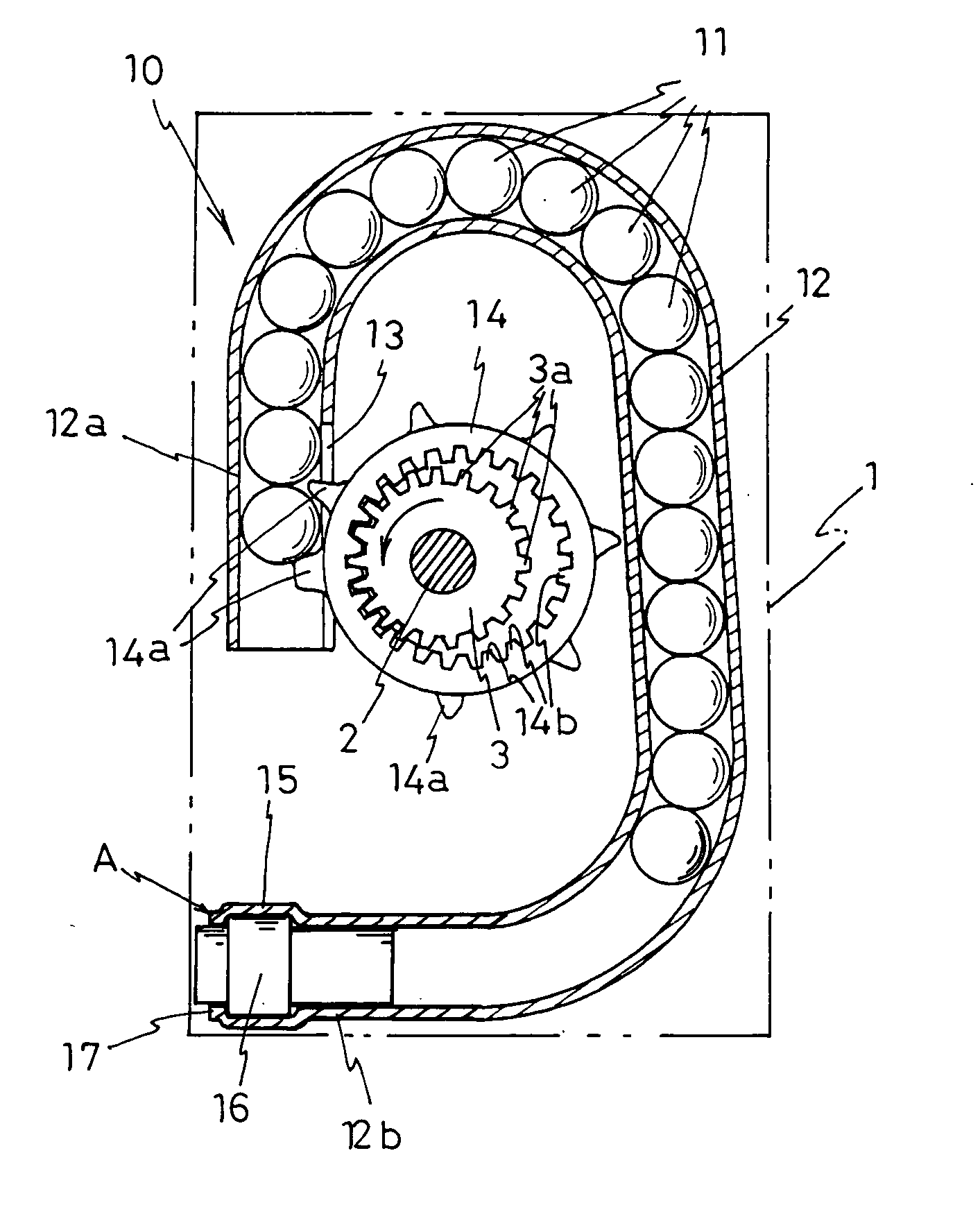
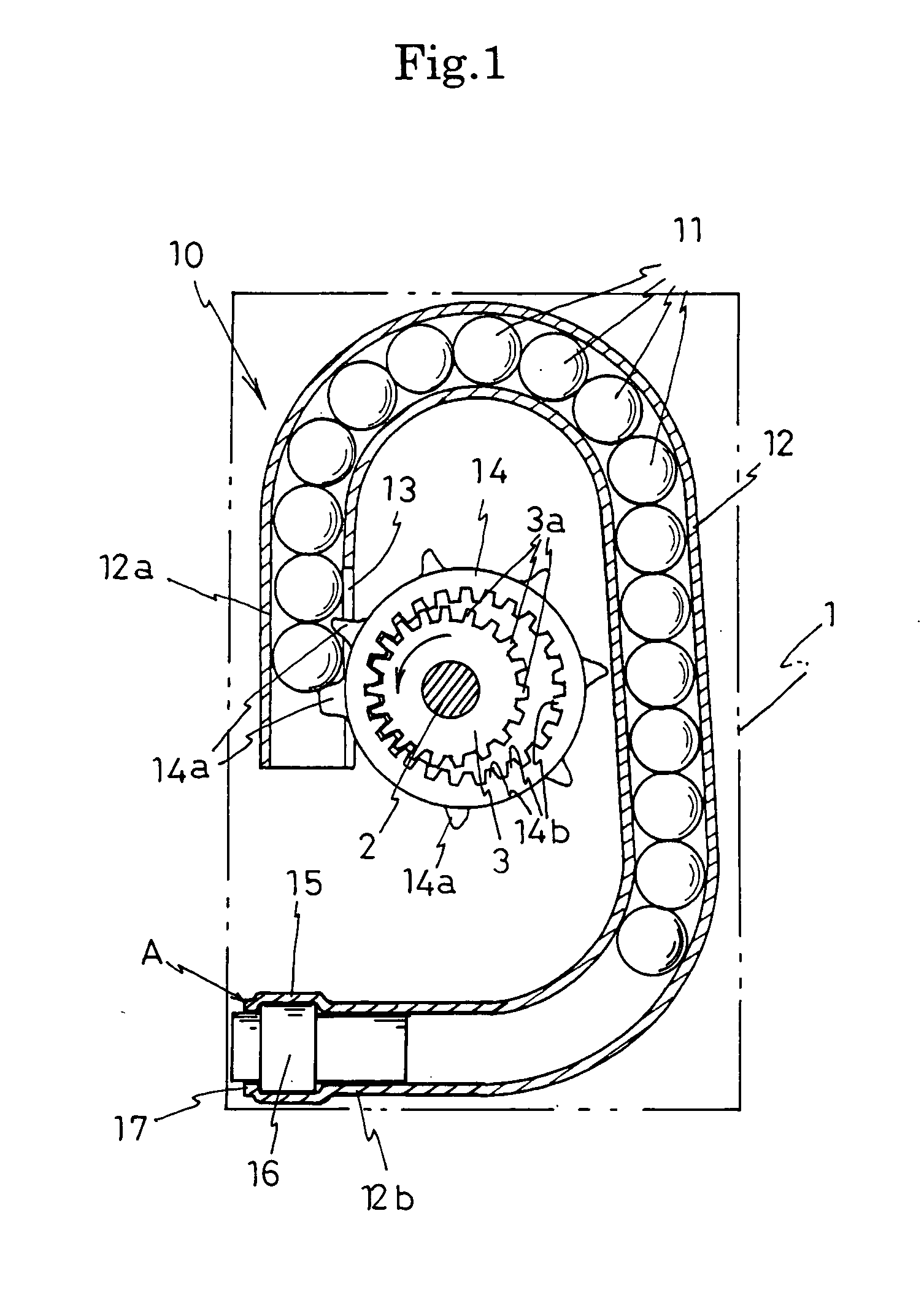
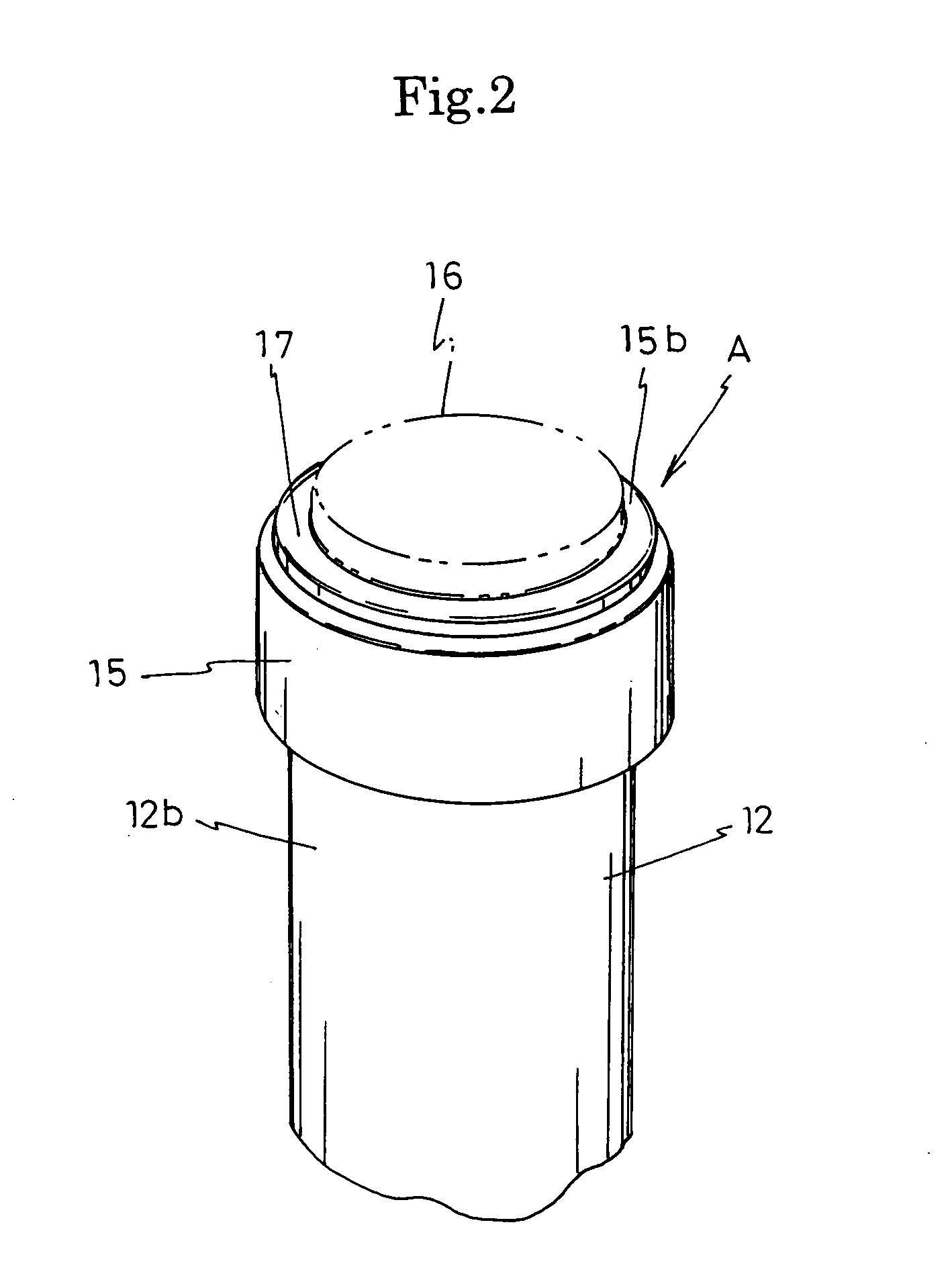
[0040] Using the method for the affixing of the pretensioner gas generator pertaining to the abovementioned present invention, six pretensioners embodying the structure for the affixing of a pretensioner gas generator pertaining to the present invention and having an annular rib 17 of outer diameter 19.0 mm (outer diameter Ö0 of the large diameter part 16a of the gas generator 16 of 16.9 mm) and projecting height H1 0.45 mm (0.20 times the thickness H0 (2.20 mm) of the annular rib 17), were produced.

[0041] Following the implementation of gas generator blasting tests on three of the six pretensioners, none of the gas generators of these three pretensioners was detached from the pipe and, in addition, there were no abnormalities of any kind observed in the calked part A.

[0042] It should be noted that the quantity of explosive used in the gas generator was the usage upper limit quantity as established in recent years.

[0043] In addition, following the implementation of gas generator ...


PUM


Abstract

The provision of a structure and method for the affixing of a pretensioner gas generator by which the function of the pretensioner can be improved without the need to use an additional component part or to increase the thickness of the wall of the pipe. In the structure for the affixing of a pretensioner gas generator, a gas generator 16 is held in a pipe 12 by the expanding of the end part 12b of a pipe 12 to form a housing part 15 for the gas generator 16, the gas generator 16 is housed in the housing part 15, and the opened end 15b of the pipe 12 in the structure for the affixing of the gas generator is calked, an annular rib 17 projects outward in the axial direction from the inner circumferential edge part of the calked part A. In the method for the affixing of the gas generator, a press is used to form the abovementioned annular rib 17.

Description

BACKGROUND OF THE INVENTION [0001] 1. Field of the Invention [0002] The present invention relates to a structure and method for the affixing of a pretensioner gas generator used in seat belt devices fitted in vehicles such as cars. [0003] 2. Description of the Related Art [0004] Seat belt devices are provided in vehicles such as cars as means for protecting the passenger at moments of sudden acceleration or deceleration. The modern seat belt device comprises a pretensioner for, when the vehicle is subject to impact such as at moments of collision, retracting the seat belt further than the state in which it has been fastened by the passenger and restraining the passenger against the seat belt with a powerful force. [0005] Although a range of systems of pretensioner are available, one such system is a gas pressure-type pretensioner comprising a gas generator that generates a high-pressure gas at the moment of collision of the car, a driving member such as balls or the like that retrac...

Claims


Application Information

Patent Timeline
IPC IPC(8): B60R22/46
CPCB60R2022/4642B60R22/4628
Inventor KAMEDA, SHIGETSUGUMIYAKE, YASUMASAHOSHI, MASAYUKI
Owner SANOH IND CO LTD
Learn More