System and method for providing controlled illumination during detected hazardous conditions

a technology for hazardous conditions and controlled illumination, applied in signalling systems, electric transmission signalling systems, instruments, etc., can solve the problems of confusion and panic of consumers to its greatest extent, confusion and panic may only be exacerbated, confusion and panic may only be reduced, etc., to reduce consumer confusion and ensure safe exi

Inactive Publication Date: 2005-07-14
ROBERTSHAW CONTROLS CO
View PDF15 Cites 3 Cited by
  • Summary
  • Abstract
  • Description
  • Claims
  • Application Information

AI Technical Summary

Benefits of technology

[0007] In view of the above, the system of the present invention provides a new and improved threat detection system that aids in the reduction of consumer confusion and safe exit from a dwelling in which a threat has been detected. More particularly, the present invention provides a new and improved threat detection system that communicates with a lighting control system to provide illumination of the dwelling during the detected threat condition. Still more particularly, the present invention provides new and improved threat detection system that interfaces with a lighting control system to provide coordinated lighting of the dwelling during the detected threat condition so as to aid in the safe escape from the dwelling.

Problems solved by technology

While the lifesaving benefits of such hazardous condition detectors cannot be disputed, they often cause great consumer confusion and panic when they sound their alarm, especially at night.
This confusion and panic may occur to its greatest extent when the consumer is awakened from sleep by the sounding of the hazardous condition alarm.
This confusion and panic is only exacerbated by the darkness as most consumers do not sleep with many lights, if any, turned on.
Knowing that time is short, and often fearing for the safety of their loved ones, these consumers may be injured as they rush around in the darkness in response to the hazardous condition alarm.
While most consumers are familiar enough with their dwelling to know where to find safe exits, the darkness and confusion of the situation may cost the consumer valuable time in choosing a safe exit path to reach such exits.
Unfortunately, such emergency lights often add to the consumer confusion as they are typically sparsely located throughout the hotel, etc., are glaring, and often shine into the consumer's eyes based on the emergency lighting being located typically on walls near the ceiling.
Since smoke rises, such location often makes visibility more difficult, similar to turning on a car's high beam lights while driving in fog.

Method used


Image

  • System and method for providing controlled illumination during detected hazardous conditions
  • System and method for providing controlled illumination during detected hazardous conditions
  • System and method for providing controlled illumination during detected hazardous conditions

Examples


Embodiment Construction

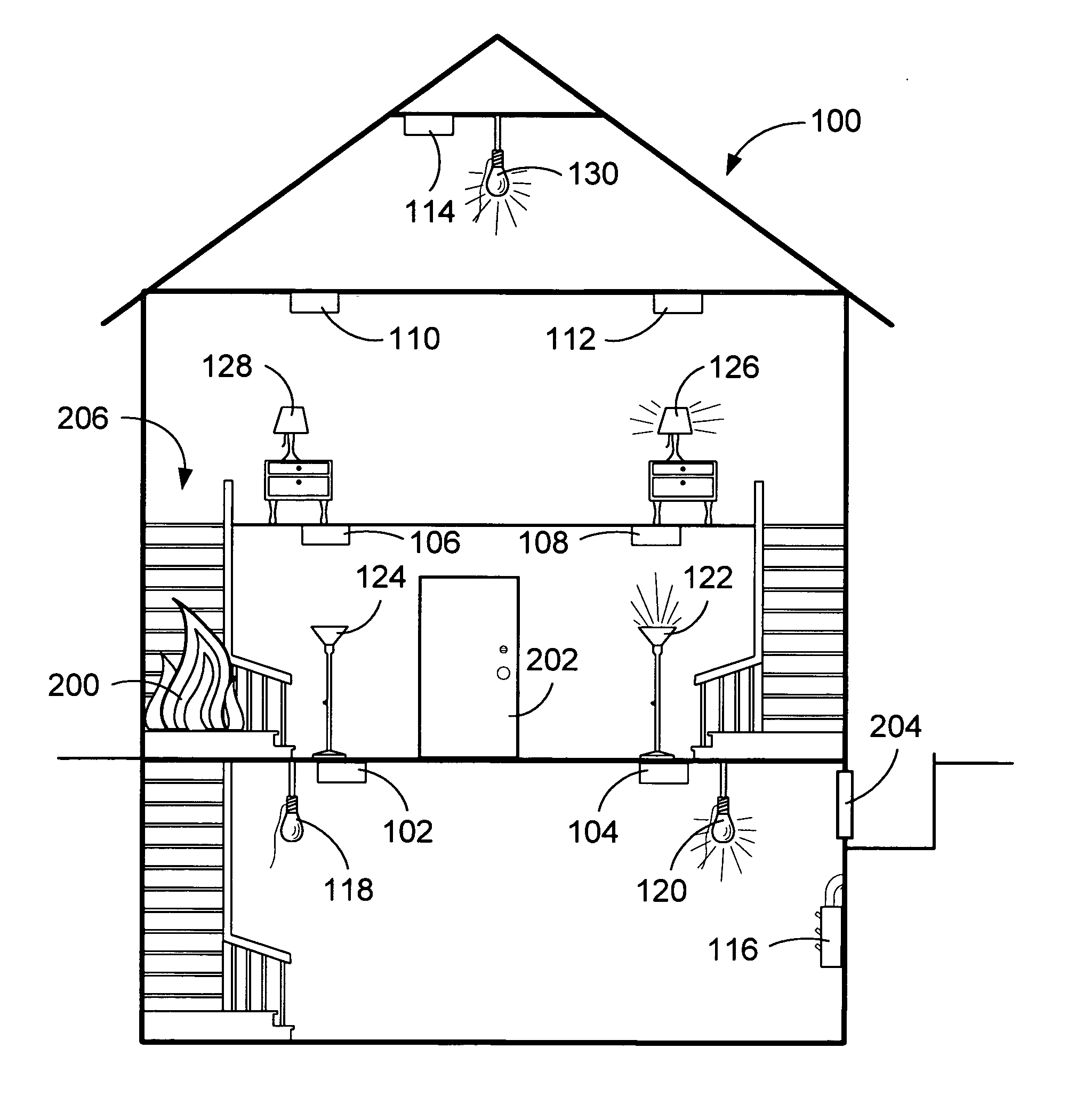
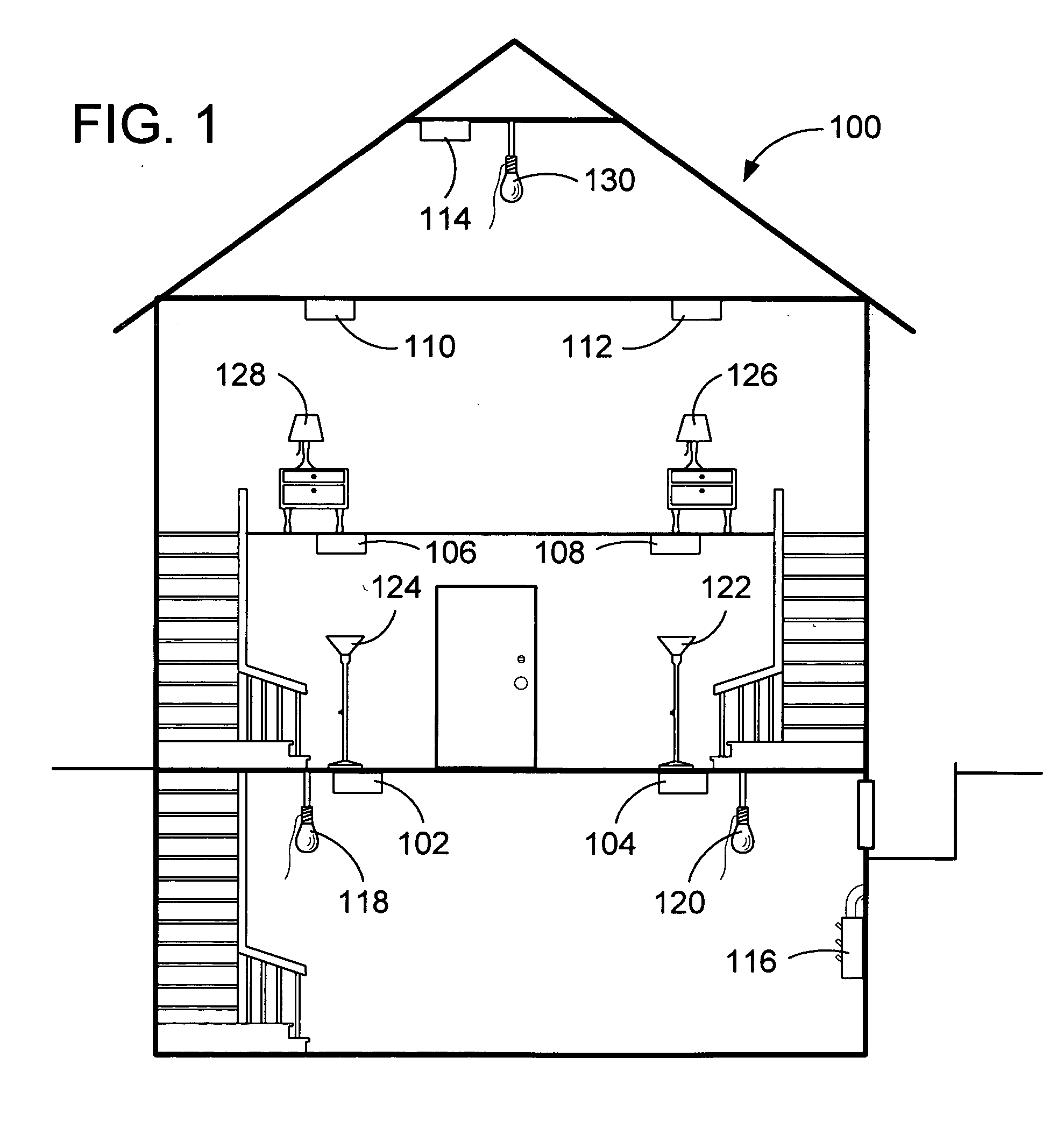
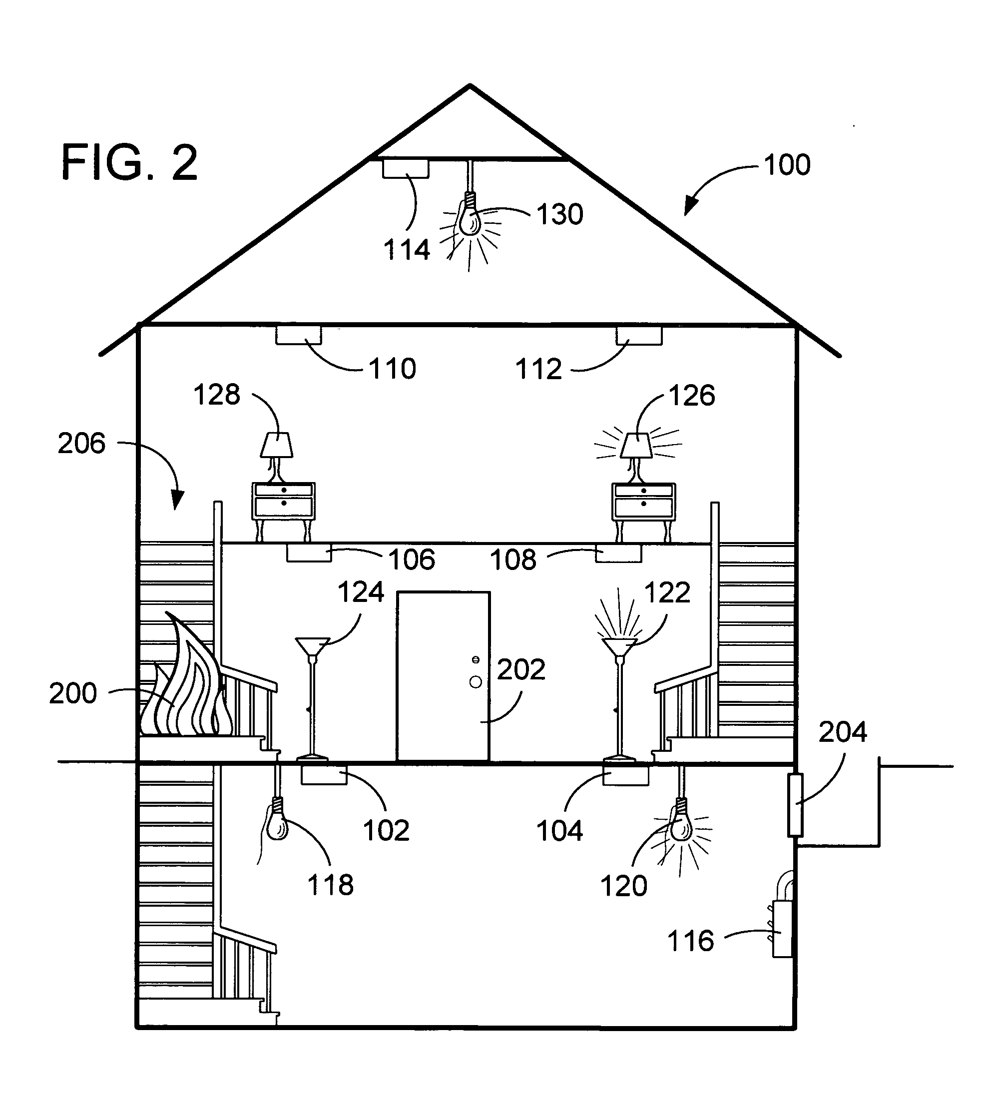
[0015] While the system of the present invention may be utilized in various commercial and residential structures, the following description will utilize the simplified dwelling 100 illustrated in FIG. 1 to explain the principle of operation and various features enabled by the present invention. However, it should be noted that the invention finds equal applicability in commercial structures, apartment buildings, hotels, etc., wherein it is desired to lessen consumer confusion and increase the probability of safe exit from the building in which a threat, such as a fire, has been detected.

[0016] Utilizing this simplified dwelling structure 100 of FIG. 1, it can be seen that the system of the present invention utilizes a number of threat detectors 102-114 located within the dwelling. While the system of the present invention provides enhanced functionality when a plurality of threat detectors 102-114 are utilized throughout the dwelling 100, many of the advantages of the present inve...


PUM


Abstract

An integrated lighting control and threat detection system is provided. Once one of the threat detectors determines that a hazardous condition exists, it transmits a threat message to the lighting control system. The lighting control system then operates to turn on illumination within the dwelling to aid in an occupant's safe exiting from the dwelling. The lighting control system operates to illuminate all lights within a dwelling upon detection of a hazardous condition. Alternatively, the lighting control system operates to illuminate preselected paths of lighting as programmed by a user. Still further, coordinated illuminated control may be provided based upon the location of the detected hazardous condition and the fixed and portable lights within a dwelling. Both fixed and adaptive illumination control are provided as is a fail safe illumination of all lights within a dwelling should each of the pre-selected exit paths contain a hazardous condition.

Description

CROSS-REFERENCE TO RELATED PATENT APPLICATIONS [0001] This patent application claims the benefit of U.S. Provisional Patent Application No. 60 / 535,424, filed Jan. 8, 2004, the teachings and disclosure of which are hereby incorporated in their entireties by reference thereto.FIELD OF THE INVENTION [0002] The present invention relates generally to hazardous condition detectors, and more particularly to networked hazardous condition detectors that enable controlled illumination during a detected hazardous condition. BACKGROUND OF THE INVENTION [0003] Recognizing the lifesaving benefits of smoke and other hazardous condition threat detectors, more and more consumers are installing these devices in their homes. Indeed, many municipalities have enacted building ordinances that require that smoke detectors be installed in new construction and in order to sell an existing home. Apartment buildings and other commercial structures typically also include such smoke and other threat detectors. ...

Claims


Application Information

Patent Timeline
Patent Type & Authority Applications(United States)
IPC IPC(8): G08B5/36G08B7/06
CPCG08B7/066
Inventor CHAPMAN, JOHN GILMAN JR.ASHWORTH, NICHOLASBURT, ROBERTWALLAERT, TIMOTHY E.
Owner ROBERTSHAW CONTROLS CO
Why Eureka
Try Eureka