
Ink container for an ink jet cartridge

a technology of ink container and ink jet cartridge, which is applied in the field of improvement of ink container for ink jet cartridge, can solve the problems of cumbersome inserting movement, reduced or lost user control of the container and/or the stability of the container during manipulation thereof, and achieves the effects of improving the ability to filter contaminants, improving the control of the flow of ink, and improving the control of the container

Inactive Publication Date: 2005-07-14
NU KOTE INT
View PDF8 Cites 3 Cited by
  • Summary
  • Abstract
  • Description
  • Claims
  • Application Information

AI Technical Summary

Benefits of technology

[0005] In accordance with the present invention, an ink container is provided by which the foregoing and other disadvantages of ink containers heretofore available are advantageously minimized or overcome. More particularly in this respect, and in accordance with one aspect of the invention, an ink container for an ink jet cartridge has a cover at the upper end thereof providing a flat surface which is textured to facilitate stabilizing a user's handling and manipulation of the container during insertion and removal thereof relative to a casing. The texturing can be provided, for example, by serrations in the material of the cover, or a layer of rubber or the like on the top surface of the cover. Such texturing promotes frictional interengagement between the container and a user's finger and, preferably, the texturing extends partially across the top surface from the front end of the container towards the rear end thereof so as to optimize the area of available contact on the container for a user's finger. When the texturing is in the form of ribs or serrations integral with the cover they preferably extend transverse to the opposite sides of the container.
[0007] In accordance with yet another aspect of the invention, a filtering pad is positioned in each of the ink chambers between the outlet port thereof and the corresponding ink absorbing block. The felt pad advantageously filters particulate material from the ink and / or foam or any particulate materials adhering to the walls of the container during the manufacturing and / or assembly process with respect thereto. Further, the felt pad has a high capillarity which allows for an increase flow of ink out of the corresponding outlet port, a higher efficiency of the absorbent media, and less wasted ink.
[0009] Another object is the provision of an ink container of the foregoing character wherein the ability to control and stabilize the container during manipulation thereof for insertion and removal relative to a casing of the ink jet cartridge is improved.
[0010] A further object is the provision of an ink container of the foregoing character wherein guidance of the container relative to the casing during insertion of the container thereinto is improved.
[0011] Yet another object is the provision of an ink container of the foregoing character with an improved ability to filter contaminants in the ink, ink absorbent media, and / or the container from flow with the ink from the container.
[0012] Still another object is the provision of an ink container of the foregoing character having a felt pad interposed between the ink absorbent block and outlet port of each ink chamber to provide a filter for the corresponding chamber and to promote control of the flow of ink from the chamber to promote faster printing and less wasted ink.

Problems solved by technology

In an ink jet cartridge of the foregoing character, gripping of the container to facilitate insertion and removal thereof relative to the casing is difficult even though a projection or finger is provided at the upper end of the container to facilitate handling thereof.
In this respect, the finger provides a single point of contact for a user's forefinger, and the latter can readily slide relative to the finger during manipulation of the container relative to the casing, whereby the user's control of the container and / or the stability with respect to the support of the container during manipulation thereof can be reduced or lost.
Further, the guidance of the container into the casing by sliding the container inwardly across the upper edge of the front wall of the casing and then downwardly in sliding engagement with the rear wall of the casing causes the inserting movement to be cumbersome and requires two points of engagement between the container and casing during the majority of the inserting operation.
Still further, the direct interfacing between the ink absorbing material and outlet ports in the ink chambers fails to provide adequate protection against contaminants being dispensed with the ink, such as contaminants in the ink and / or foam material and / or in the container from the manufacturing process.
Moreover, there is a less than desirable flow of ink from the foam material or other absorbent media which results in wasted ink.

Method used


Image

  • Ink container for an ink jet cartridge
  • Ink container for an ink jet cartridge
  • Ink container for an ink jet cartridge

Examples


Embodiment Construction

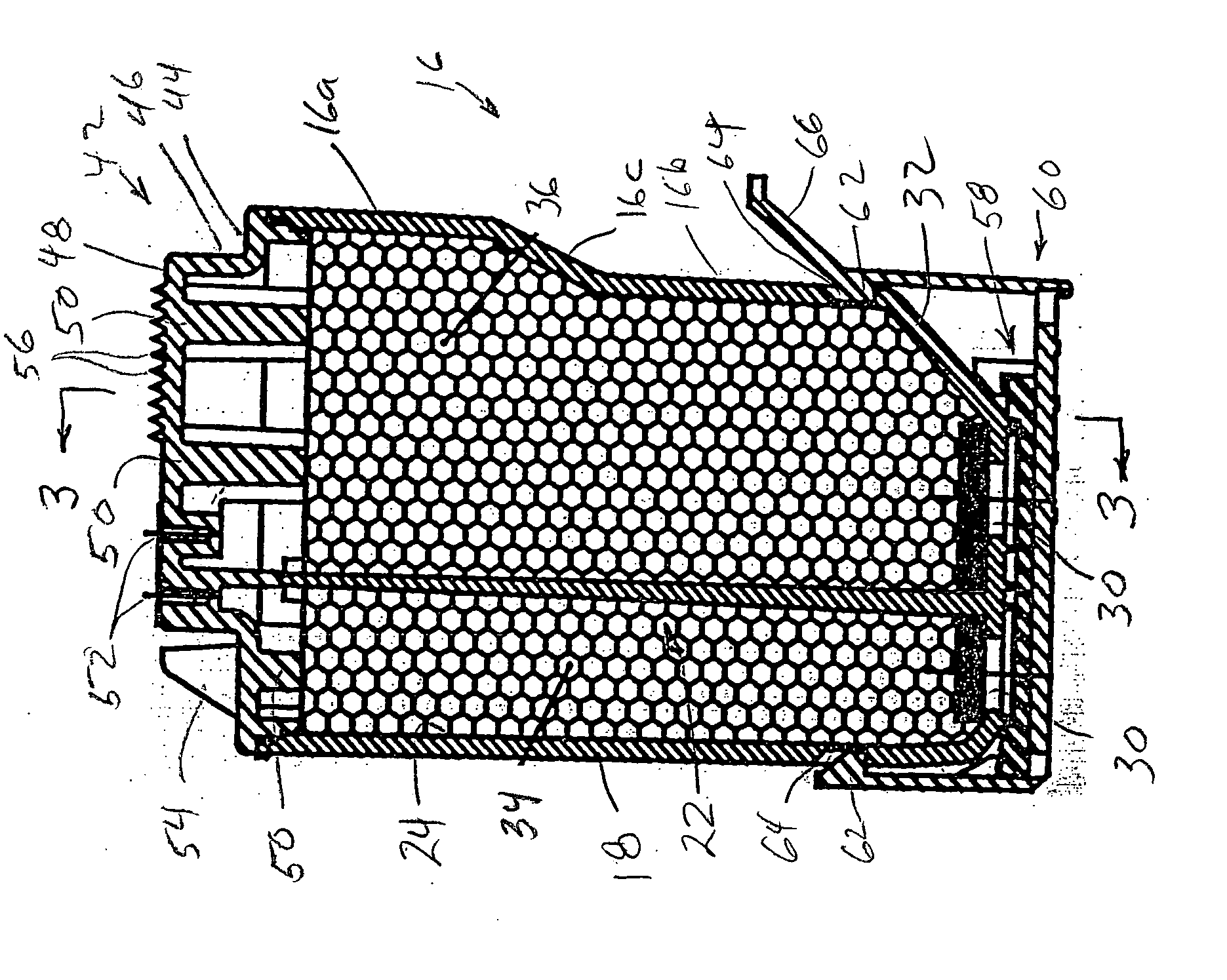
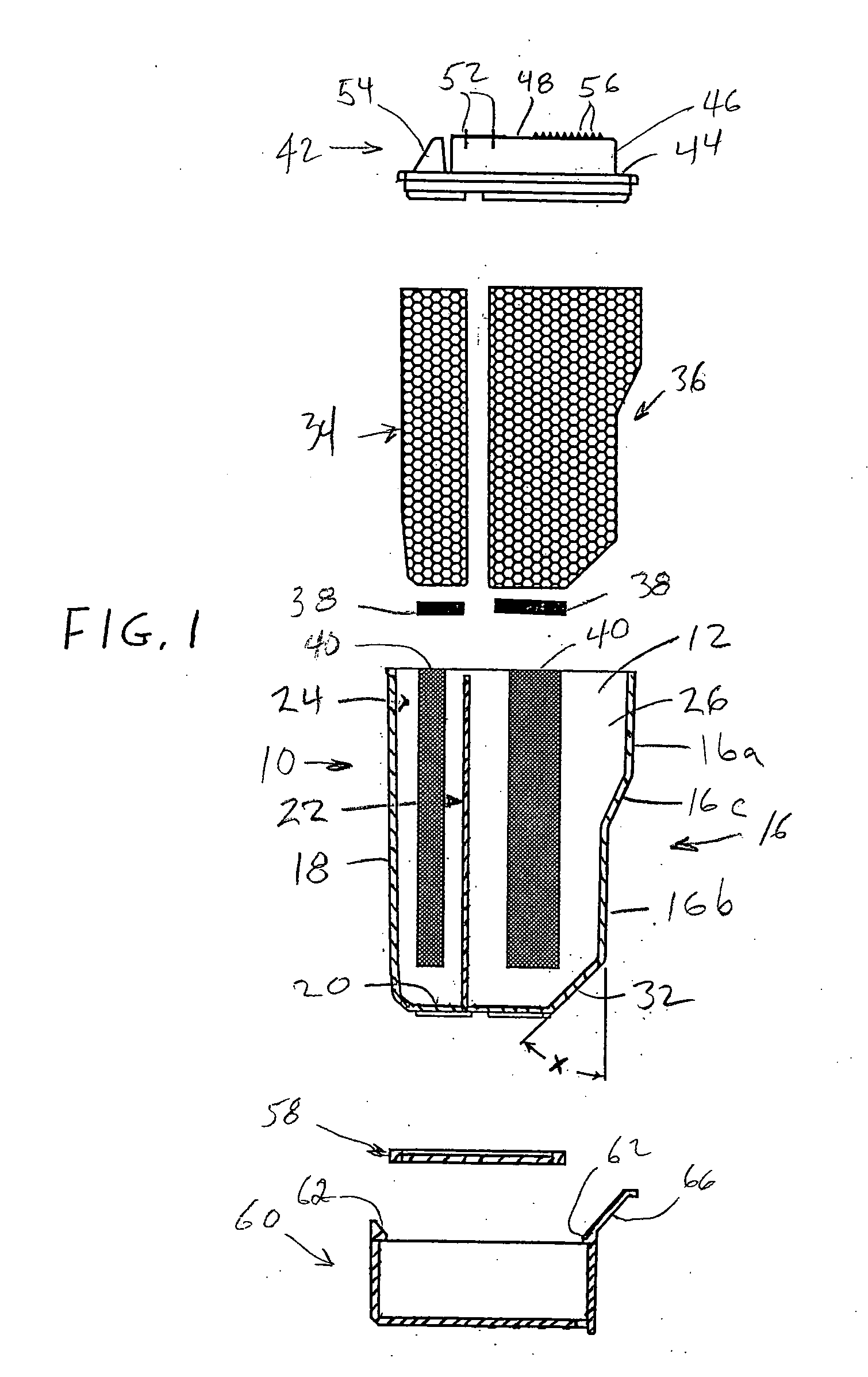
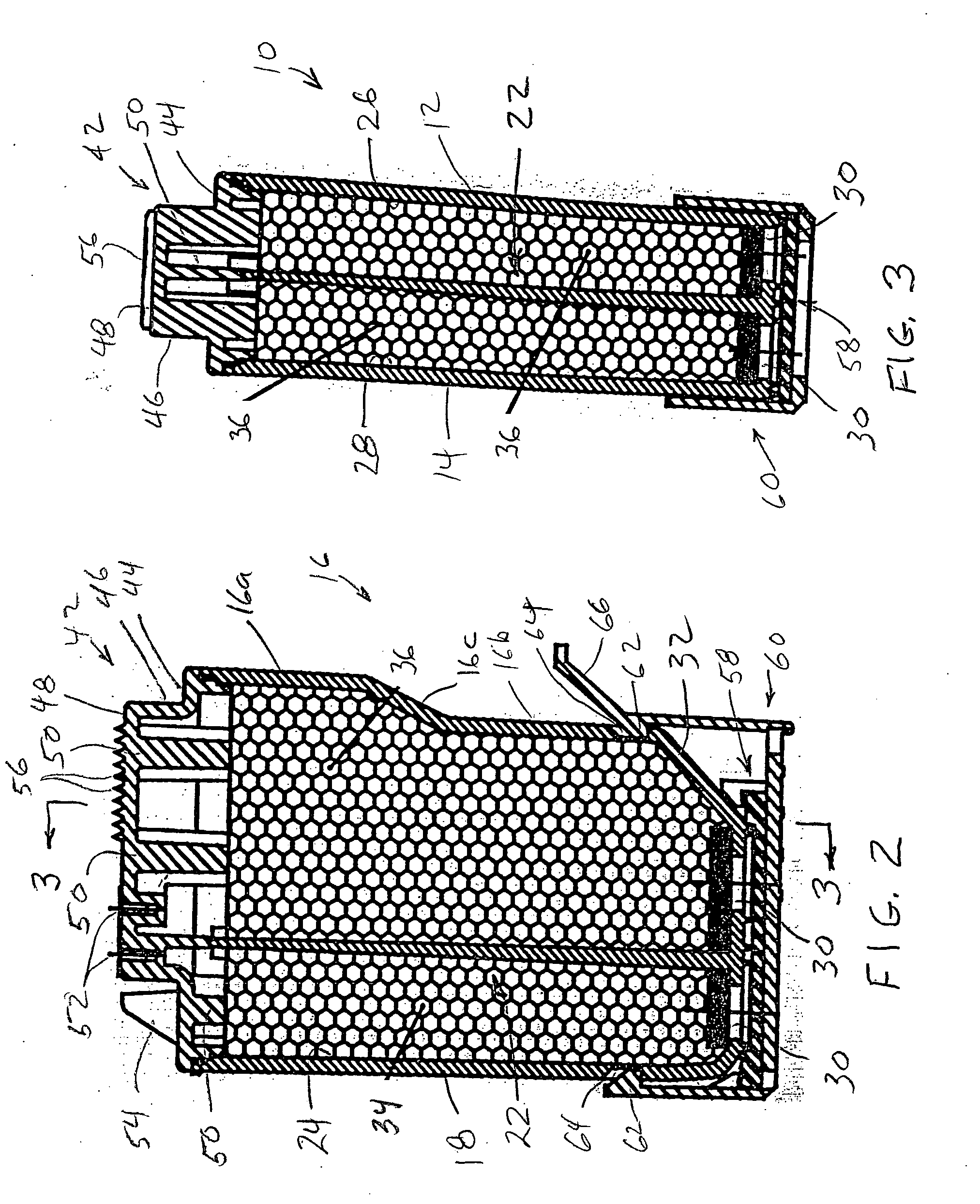
[0020] Referring now in greater detail to the drawings, wherein the showings are for the purpose of illustrating preferred embodiments of the invention only, and not for the purpose of limiting the invention, an ink container is shown which comprises a shell 10 having a pair of spaced apart side walls 12 and 14, a front wall 16, a rear wall 18, and a bottom wall 20. Shell 10 is divided interiorly by a T-shaped partition 22 into three ink chambers 24, 26 and 28, each of which is provided with a corresponding outlet port 30 in bottom wall 20. Front wall 16 of the shell has upper and lower portions 16a and 16b, respectively, offset by an intermediate wall portion 16c. Front wall portion 16b and bottom wall 20 lie in planes which are generally perpendicular to one another and, for the purpose set forth hereinafter, a planar guide wall 32 extends between and at an angle x to front wall portion 16b and bottom wall 20. Preferably, angle x is 45°, and guide wall 32 intersects front wall por...


PUM


Abstract

An ink container for an inkjet cartridge comprises spaced apart side walls, a front wall, a rear wall and a bottom wall, and a partition dividing the interior into three ink chambers. Each chamber includes an outlet port in the bottom wall, and the front wall and bottom wall lie in generally perpendicular planes, and a planer guide wall extends between and at an angle to the front and bottom walls. Each chamber contains a block of ink absorbent material and a felt filter pad between the corresponding block and outlet port, and the container further includes a cover having a flat upper surface provided with serrations to enhance gripping the container.

Description

BACKGROUND OF THE INVENTION [0001] This invention relates to the art of ink jet printers and, more particularly, to improvements in an ink container for an ink jet cartridge. [0002] As is known, an ink jet cartridge comprises an ink container or tank removably received in a casing having ink tapping components in the bottom thereof for interconnection with ink outlet ports in the bottom wall of the container. The ink container is comprised of spaced apart side walls, a front wall, a rear wall, and a bottom wall, and the upper end of the container is closed by a cover which is heat sealed in place following the filling of the interior with ink. For color printing, the interior of the container is partitioned to define a plurality of chambers, each for a different color ink, and each of the chambers has an outlet port in the bottom wall for communication with a corresponding ink tapping component in the casing. The interior of each chamber is provided with a block of ink absorbing mat...

Claims


Application Information

Patent Timeline
Patent Type & Authority Applications(United States)
IPC IPC(8): B41J2/175
CPCB41J2/17513
Inventor ANDERSEN, STEPHEN A.LENGYEL, DENNIS M.
Owner NU KOTE INT
Learn More