
Quick connector

Active Publication Date: 2005-07-14
TOKAI RUBBER IND LTD
View PDF3 Cites 36 Cited by
  • Summary
  • Abstract
  • Description
  • Claims
  • Application Information

AI Technical Summary

Benefits of technology

[0009] The wire retainer may be configured to engage or engage in a mounting direction with circumferential end portion or circumferential end or edge of the engagement slits when moved in the retracted position. This permits to maintain the wire retainer in the retracted position with simple configuration of the quick connector.
[0012] As described above, according to the present invention, there is provided a novel quick connector having sufficient strength wherein a wire retainer include engagement arms largely projecting inwardly so as to block escape of a pipe.

Problems solved by technology

When the distance or divider portion is sized small, there is a little possibility to adversely affect situating of the engagement arms of the wire retainer in the engagement slits.
Therefore, it is required to provide the quick connector with restraining means so as to maintain the wire retainer in the mounted position and not to allow the wire retainer to move or be displaced out of the retracted position in a pull out direction.
However, when the wire retainer is formed to have the engagement portions extending axially and the connector housing is formed or ensured with restraining portions to be engaged with the engagement portions, this might result in a retainer mounting portion of the connector housing extending improperly long in an axial direction, restraining portions being configured with insufficient restraining function, or any other inconvenience.
However, an axial portion which is defined on the leading portion of the engagement arm does not allow the engagement arm to enter the engagement slit including the divider portion, and make it difficult to fit or mount the wire retainer to the connector housing.

Method used


Image

  • Quick connector
  • Quick connector
  • Quick connector

Examples


Embodiment Construction

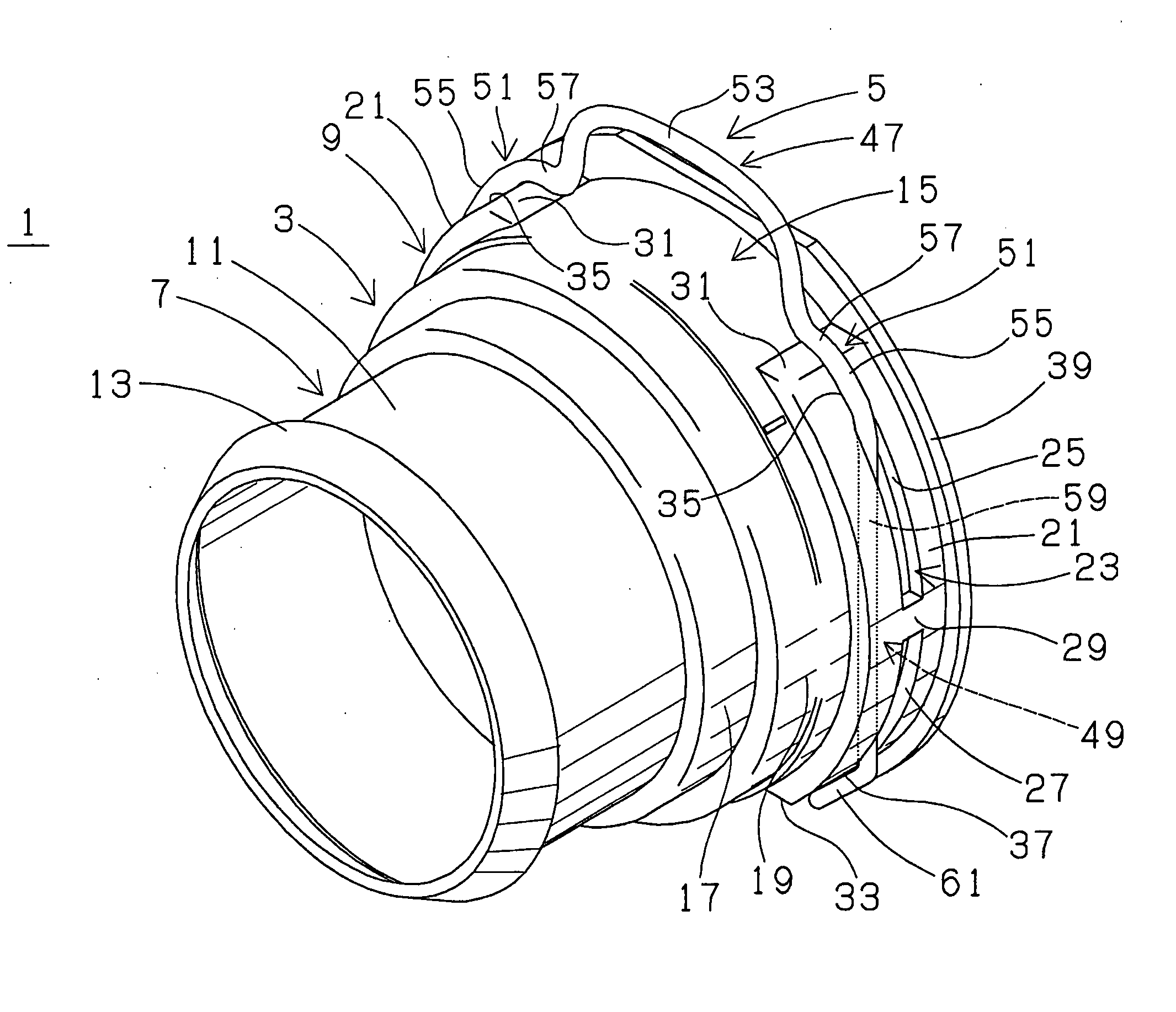
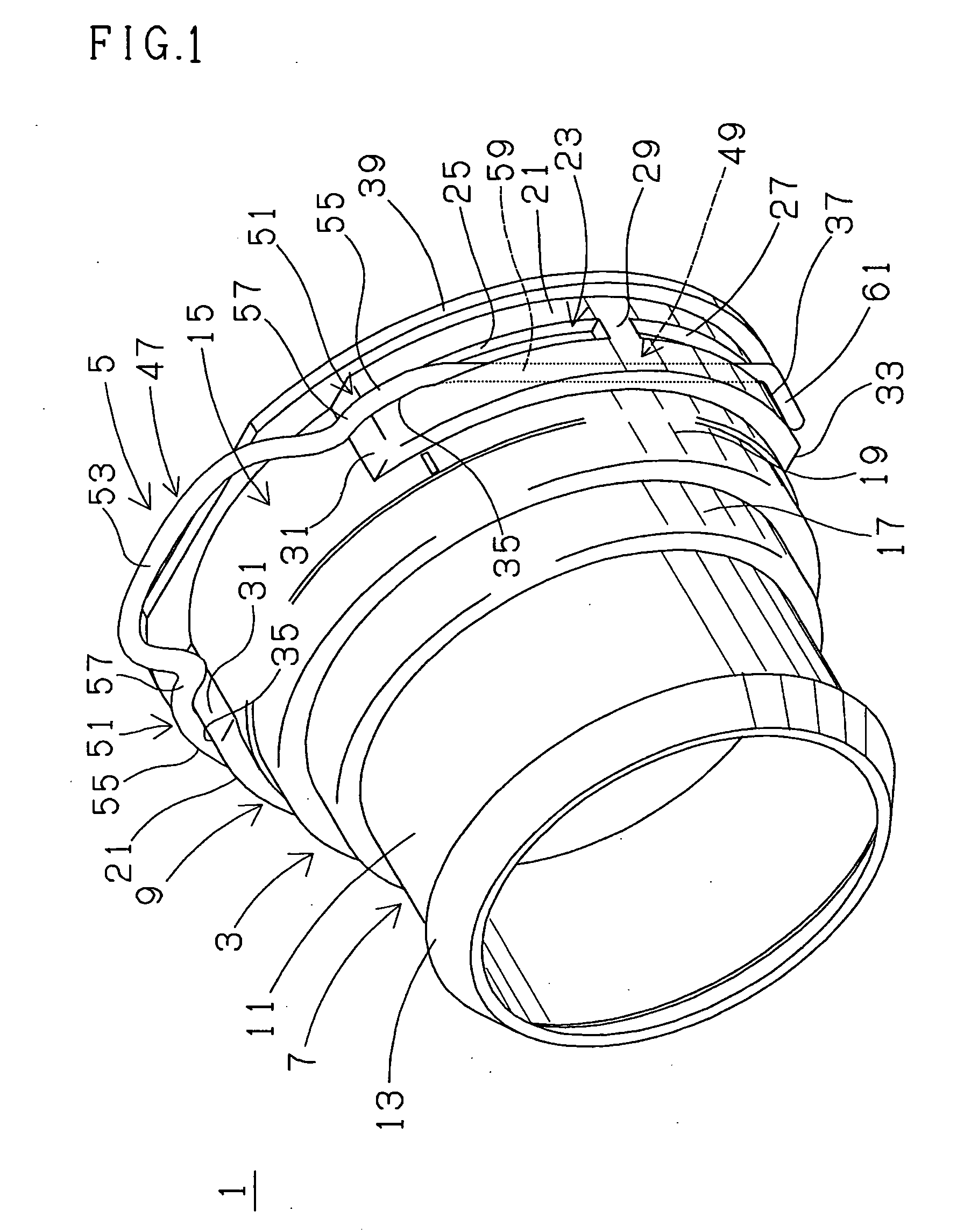
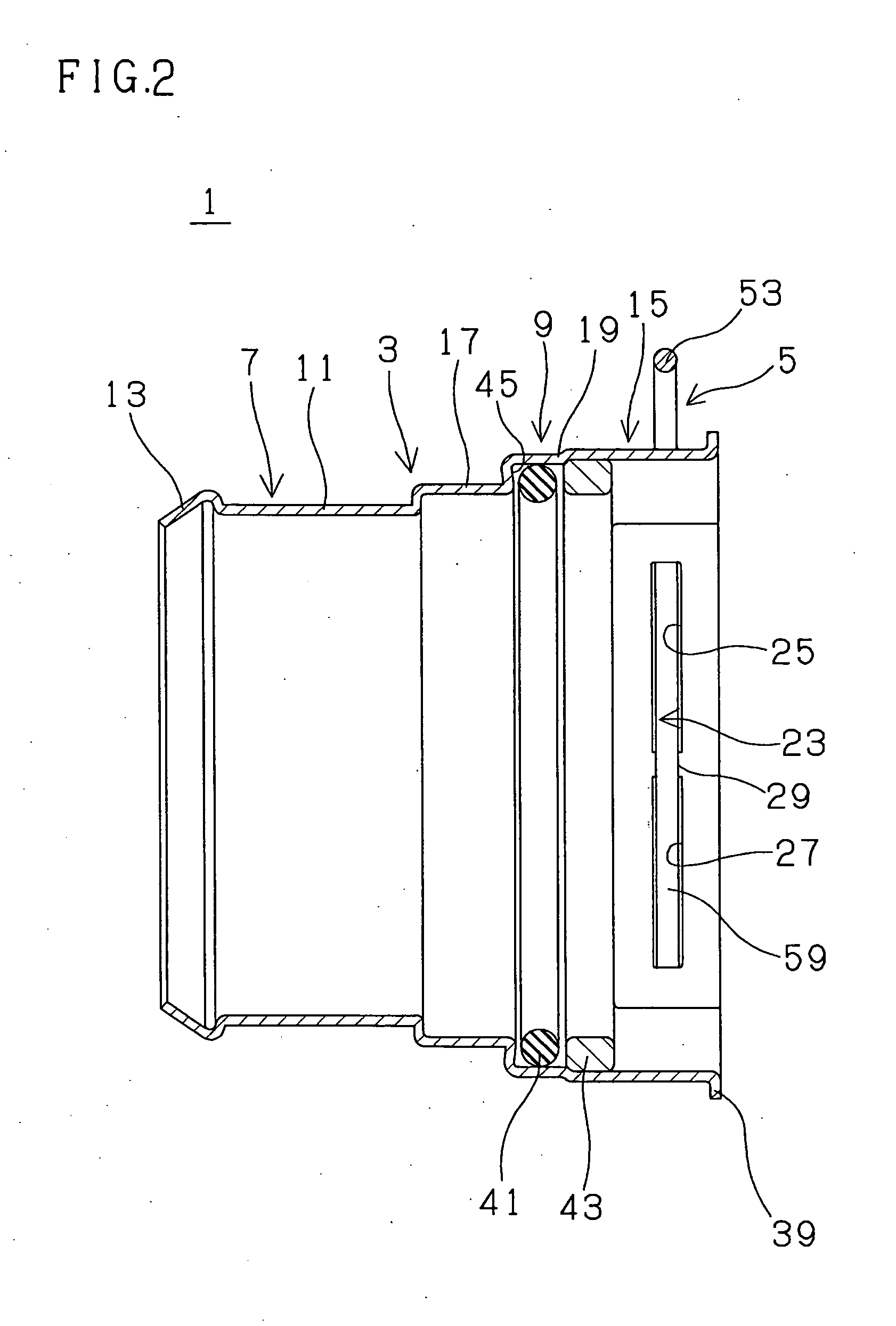
[0032] A first quick connector 1 is adapted, for example, for assembly in air supply and exhaust piping of an automobile. As well understood specifically from FIGS. 1 to 3, the first quick connector 1 comprises a first tubular connector housing 3 which is thin-walled, a wire retainer 5 of horseshoe shape or generally of horseshoe shape mounted on the first connector housing 3. The first connector housing 3, for example, made of metal, has a cylindrical hose connecting portion 7 (connecting portion) on one axial end of the first connector housing 3 (namely on a side in one direction of an axis thereof) and a generally cylindrical pipe inserting portion 9 on an opposite axial end of the first connector housing 3 (namely on a side in an opposite direction of an axis thereof) as a unit. The first connector housing 3 is formed large in diameter and relatively short in axial length to join a hose of large diameter and a pipe of large diameter.

[0033] The hose connecting portion 7 includes...


PUM


Abstract

A first quick connector is provided with a connector housing and a wire retainer. The connector housing has a retainer mounting portion which is formed with engagement slits. The wire retainer is mounted on the retainer mounting portion such that engagement arms enter the engagement slits and project in the retainer mounting portion. Each of the engagement slits has a first slit part on one circumferential end and a second slit part on the other circumferential end with intervening a divider portion therebetween.

Description

BACKGROUND OF THE INVENTION [0001] 1. Field of the Invention [0002] The present invention relates to a quick connector, for example, to be adapted for assembly in piping of an automobile. [0003] 2. Description of the Related Art [0004] In a fluid piping system where a pipe and a hose are joined, a connector is used for joining a pipe and a hose. In such piping system, a connector has a tubular connector housing including a connecting portion on one axial end to be connected to a hose. And, for example, a pipe includes an inserting end portion on an inserting end thereof wherein an annular engagement projection is formed on and around an outer peripheral surface, retainer means is provided on an opposite axial end of the connector housing for snap-engagement, and thereby the connector is configured as quick connection type. Then, the inserting end portion of the pipe is inserted into an opening on an end of the connector housing so that the annular engagement projection snap-engages ...

Claims


Application Information

Patent Timeline
IPC IPC(8): F16L37/14F16L37/088
CPCF16L37/088F02M35/10144F02M35/10354F16L37/0885F16L37/0841F16L37/144
Inventor TAKAYANAGI, AKIRAMORI, HIROYOSHINISHIMURA, MOTOHIDE
Owner TOKAI RUBBER IND LTD
Learn More