Method of producing brush-like grind stone, the brush-like grind stone, and brush for grind machine

a technology of grinding stone and grinding stone, which is applied in the direction of grinding device, manufacturing tool, flexible wheel, etc., can solve the problems of poor polishing efficiency, burrs, work marks, etc., and achieve the effect of improving work precision, reducing conformability and grindability changes, and stable working precision

Active Publication Date: 2005-07-14
XEBEC TECH CO LTD +1
View PDF17 Cites 25 Cited by
  • Summary
  • Abstract
  • Description
  • Claims
  • Application Information

AI Technical Summary

Benefits of technology

[0029] With this configuration, even when the wire-shaped grinding elements attempt to escape to the external peripheral side, they bump against the interior surface of the peripheral wall of the brush case and are held back. When the wire-shaped grinding elements attempt to escape to the interior peripheral side, they bump against the external peripheral side of the spindle and are held back, and the range of escape is narrowed by the protrusions. As a result, there is no difference in the extend of escape between the wire-shaped grinding elements positioned on the external peripheral side and the wire-shaped grinding elements positioned on the interior peripheral side. The situation in which the wire-shaped grinding elements positioned on the interior peripheral side become less abrasive can therefore be avoided because no difference in rigidity is exhibited betwe

Problems solved by technology

However, after these precision machines have worked, burrs, work marks, tool marks, or the like are always present, so post-working is required to remove these.
However, nylon brushes with abrasive grains, brass brushes, wire brushes, shot blasts, barrels, paper, or the like, used in conventional working have drawbacks in that removal efficiency of these burrs, work marks, and the like, and the polishing efficiency is poor.
Conventional post-working tools have poor working accuracy, and have drawbacks in that burrs, work marks, and the like are left, and there is great variation in the manufacturing quality after working.

Method used


Image

  • Method of producing brush-like grind stone, the brush-like grind stone, and brush for grind machine
  • Method of producing brush-like grind stone, the brush-like grind stone, and brush for grind machine
  • Method of producing brush-like grind stone, the brush-like grind stone, and brush for grind machine

Examples


embodiment 1

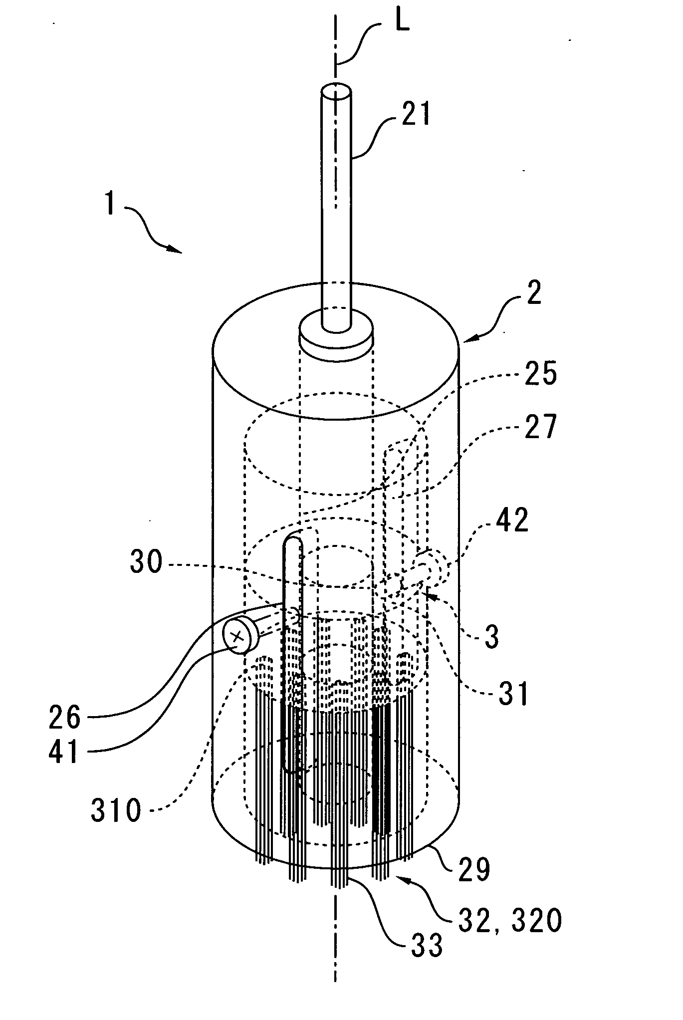
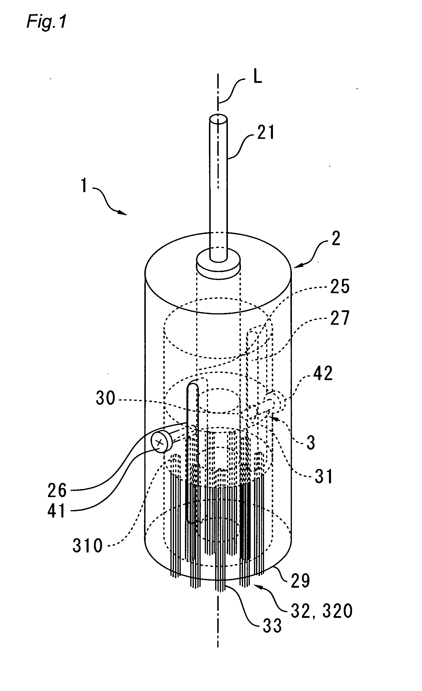
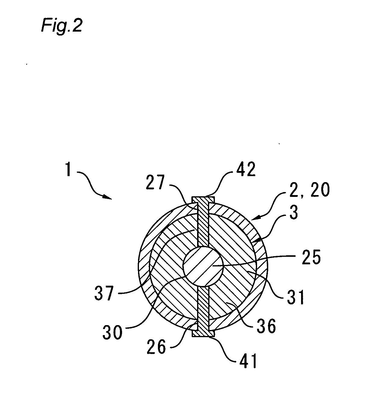
[0063]FIG. 1 is a diagram depicting a state in which an upper portion (holder side) of a brush-shaped grindstone is inserted and fixed in an interior of a brush case in a polisher brush wherein the present invention has been applied. FIG. 2 is a cross-sectional view through a section in which the polisher brush depicted in FIG. 1 is fixed in place with screws. FIG. 3 is a bottom view of the polisher brush depicted in FIG. 1. FIG. 4 is an exploded perspective view depicting a state in which the polisher brush depicted in FIG. 1 is disassembled into the brush case and the brush-shaped grindstone. FIGS. 5(A), (B), (C), and (D) are, respectively, a diagram depicting a state in which a surrounding region where the guide holes open is made into a flat surface on an external peripheral surface of a peripheral wall of the brush case in the polisher brush depicted in FIG. 1; a diagram depicting a state in which a surrounding region where a leading end portion of an axle portion of a screw ma...

embodiment 2

[0085] FIGS. 7(A) and (B) are, respectively, a diagram and a bottom view that schematically depict the polisher brush related to embodiment 2 of the present invention.

[0086] In the present embodiment, a discoid projecting portion 50 that projects to the external peripheral side is attached to the lower end side of the spindle 25 with screws 55, screw stops, or the like so as to allow easy removal, as shown in FIGS. 7(A) and (B). The other features of this structure are the same as embodiment 1, and are therefore omitted from the description.

[0087] In the present embodiment, when the wire-shaped grinding elements 32 attempt to escape to the external peripheral side, they bump against the interior surface of the peripheral wall 20 of the brush case 2 and are held back, and when the elements attempt to escape to the interior peripheral side, they bump against an external peripheral surface of the projecting portion 50 disposed on the spindle 25 and are held back. As a result, there i...

embodiment 3

[0089] FIGS. 8(A) and (B) are, respectively, a diagram and a bottom view that schematically depict the polisher brush related to embodiment 3 of the present invention.

[0090] In the present embodiment, a projecting portion 50 that projects to the external peripheral side at the lower end side is attached to the lower end surface of the spindle 25 with screws 55, screw stops, or the like so as to allow easy removal, as shown in FIGS. 8(A) and (B); a plurality of protrusions 51 extended in a radial manner toward the external peripheral side are further formed on an external peripheral side of this projecting portion 50; and wire-shaped grinding elements 32 are evenly positioned between these protrusions 51. The other features of this structure are the same as embodiment 1, and are therefore omitted from the description.

[0091] In the present embodiment, when the wire-shaped grinding elements 32 attempt to escape to the external peripheral side, they bump against the interior surface o...


PUM


Abstract

In the manufacture of a brush-shaped grindstone (3), embedding holes (310) are formed in a grinding element holding surface (311) of a holder (31) in mutually separated positions. A base end side of a plurality of wire-shaped grinding elements (32), formed such that a composite yarn composed of inorganic filaments is impregnated and hardened with a resin, is aligned, and rod assemblies (320) are thereafter formed by fixing the base end side of the plurality of wire-shaped grinding elements (32) with adhesive (71) in holes (60) of a die material (6), which is formed to have substantially the same size as the embedding holes (310) of the holder (31). The rod assemblies (320) are thereafter embedded in the embedding holes (310) of the holder (32), and fixed with adhesive (72). Whereby, removing burrs from a precision work component, performing polishing, and the like can be carried out with good efficiency and high precision.

Description

TECHNICAL FIELD [0001] The present invention relates to a manufacturing method for a brush-shaped grindstone for deburring and polishing, to a brush-shaped grindstone manufactured with this method, and to a polisher brush that uses this brush-shaped grindstone. BACKGROUND ART [0002] Precision components primarily used in automobile parts, aircraft parts, and the like are worked with precision and high accuracy primarily by means of numerically controlled lathes, numerically controlled milling machines, machining centers, robots, special purpose machines, and other automatic machines, using end mills, drills, dies, taps, grindstones, and other tools. However, after these precision machines have worked, burrs, work marks, tool marks, or the like are always present, so post-working is required to remove these. Such post-working tools conventionally involve the use of nylon brushes with abrasive grain, brass brushes, wire brushes, shot blasts, barrels, paper, and the like. Much of the f...

Claims


Application Information

Patent Timeline
IPC IPC(8): A46B13/00B24D13/14B24D18/00B24D99/00
CPCA46B13/008A46B2200/3093A46B9/10B24D18/0072B24D13/145B24D13/14
Inventor MATSUSHITA, SUGURUSUMIYOSHI, SACHIKOSUMIYOSHI, NORIHIKOSUMIYOSHI, YOSHIHIKOODAKA, ATSUSHI
Owner XEBEC TECH CO LTD
Why Eureka
Try Eureka