Wireless communication device arrangement

a communication device and wireless technology, applied in the field of wireless communication devices, can solve the problems of significantly increasing manufacturing costs, reducing the distance between the user's head and the antenna, and reducing the rf performance of the wireless communication device, so as to reduce the complexity of the device, reduce the interference of the user's head and the antenna, and reduce the effect of em interferen

Inactive Publication Date: 2005-07-14
KYOCERA CORP
View PDF7 Cites 15 Cited by
  • Summary
  • Abstract
  • Description
  • Claims
  • Application Information

AI Technical Summary

Benefits of technology

[0011] By way of illustration, an exemplary wireless communication device comprises a housing having a front surface, a first side surface, and a second side surface. The second side surface is situated opposite the first side surface of the housing. The wireless communication device further includes an antenna situated proximate the first side surface. On the second side surface are defined first and second openings, such as a speaker opening and a microphone opening. A speaker situated within the housing transmits acoustic signals via the speaker opening, and a microphone situated within the housing receives acoustic signals via the microphone opening. With this arrangement, the user places the second side surface, rather than the front surface, against or proximate the user's head to speak into the microphone and to hear audio generated by the speaker. Advantageously, the distance between the user's head and the antenna is effectively increased, resulting in significantly reduced EM interference.
[0012] According to various embodiments, one or more of benefits may be realized by the wireless communication device arrangement including, for example, reduced device complexity, reduced device design and development time, reduced manufacturing costs, reduced hearing aid interference, improved hearing aid compatibility, improved device performance, and improved power consumption efficiency, among others, as discussed in greater detail below.

Problems solved by technology

A significant problem with the conventional arrangement described above, however, is the increased EM interference between the user's head and the antenna, which is generally mounted on the top surface of the housing and in close proximity the user's head.
Depending on the degree of EM interference, the RF performance of the wireless communication device can be significantly degraded and / or may not meet government regulations regarding wireless communications.
The shielding approach, however, increases the number of elements in the wireless communication device, resulting in significantly increased manufacturing costs.
Moreover, many shielding techniques are not very effective or otherwise consume substantial amount of experimentation and testing to achieve requisite EM relocation or spreading, which are undesirable.
This loss of EM energy, however, results in reduced device performance and increased power consumption.
Furthermore, like the shielding approach, RF absorption increases the number of elements in the wireless communication device, resulting in significantly increased manufacturing costs.
Reduced gain, however, negatively results in reduced RF performance.
Additionally, modifying the antenna structure results in increased development and design costs, as well as increased manufacturing costs.
In some cases, modifying the antenna structure results in increased form-factor of the wireless communication device which is also undesirable.

Method used


Image

  • Wireless communication device arrangement
  • Wireless communication device arrangement
  • Wireless communication device arrangement

Examples


Embodiment Construction

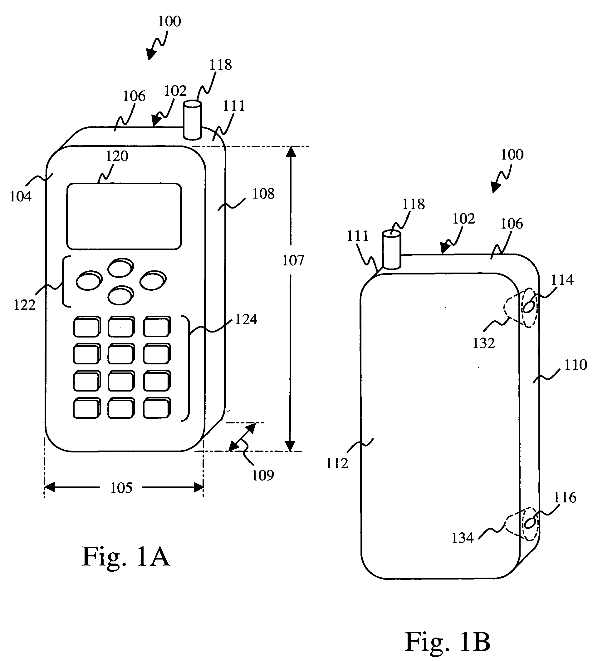
[0018] Referring first to FIGS. 1A and 1B, exemplary wireless communication device 100 according to one embodiment of the present invention is shown in front perspective view and rear perspective view, respectively. Although housing 102 of wireless communication device 100 is shown in a traditional one-piece (or “candy-bar”) shape for a mobile phone, the principles and advantages of the arrangement of wireless communication device 100 may also be applied to shapes different from that specifically shown in the Figures and discussed herein.

[0019] As shown in FIGS. 1A and 1B, housing 102 of wireless communication device 100 includes front surface 104, top surface 106, first side surface 108 and second side surface 110, where second side surface 110 is situated opposite first side surface 108. Typically, dimension 105 corresponding to the width of front surface 104 is larger than dimension 109 corresponding to the width of first and second side surfaces 108 and 110. Dimension 107, whic...


PUM


Abstract

An exemplary wireless communication device comprises a housing having a front surface, a first side surface, and a second side surface, wherein the second side surface is situated opposite the first side surface of the housing. An antenna is situated proximate the first side surface, and a speaker and a microphone are situated proximate the second side surface of the housing, which results in increased distance and EM interference between the user's head and the antenna during conversational use of the wireless communication device.

Description

BACKGROUND OF THE INVENTION [0001] 1. Field of the Invention [0002] The present invention relates to the field of communication devices. More specifically, the invention relates to wireless communication devices. [0003] 2. Related Art [0004] A typical wireless communication device, such as a mobile phone, comprises, among other things, a processor coupled to a memory and to a transceiver, each of which is mounted on a printed circuit board (“PCB”) and enclosed in a housing. A mobile power source, such as a battery, is coupled to and supplies power to the processor, the memory and the transceiver. A speaker and a microphone are also enclosed within the housing for transmitting and receiving, respectively, acoustic signals to and from a user of the wireless communication device. The wireless communication device communicates information by transmitting and receiving electromagnetic (“EM”) energy in the radio frequency (“RF”) band via an antenna coupled to the transceiver. [0005] In a ...

Claims


Application Information

Patent Timeline
Patent Type & Authority Applications(United States)
IPC IPC(8): H04M1/03
CPCH04M1/03
Inventor LI, CHIU K.
Owner KYOCERA CORP
Why Eureka
Try Eureka