Real-time measurement of tool forces and machining process model parameters

a technology of process model and tool force, applied in the field of real-time measurement of tool force and machining process model parameters, can solve the problems of prone to substantial errors, use of a dedicated device such as a piezoelectric, and inability to eliminate the need for tool force measuremen

Active Publication Date: 2005-07-14
UNIVERSITY OF NEW HAMPSHIRE +1
View PDF10 Cites 19 Cited by
  • Summary
  • Abstract
  • Description
  • Claims
  • Application Information

AI Technical Summary

Problems solved by technology

Current methods for measuring tool forces require the use of a complex and expensive dedicated device such as a piezoelectric force sensor.
Due to the complexity and expense of the force sensor, these methods of tool force measurement are most typically used in academic and laboratory studies.
However, the prediction of tool forces using cutting energies does not eliminate the need for tool force measurements.
This method provides the tool forces under a variety of cutting geometries, but is limited to the particular combination of tooling, stock, and other cutting conditions used to determine the process model parameters.
However, this extension is prone to substantial errors.
The variation in the cutting energies makes their application to tool force prediction problematic at best.
Further difficulties arise when the cutting energies found in one laboratory are transferred to other applications.
These difficulties are not usually discussed in the resea

Method used


Image

  • Real-time measurement of tool forces and machining process model parameters
  • Real-time measurement of tool forces and machining process model parameters
  • Real-time measurement of tool forces and machining process model parameters

Examples


Embodiment Construction

[0018] The embodiments set forth below represent the necessary information to enable those skilled in the art to practice the invention and illustrate the best mode of practicing the invention. Upon reading the following description in light of the accompanying drawing figures, those skilled in the art will understand the concepts of the invention and will recognize applications of these concepts not particularly addressed herein. It should be understood that these concepts and applications fall within the scope of the disclosure and the accompanying claims.

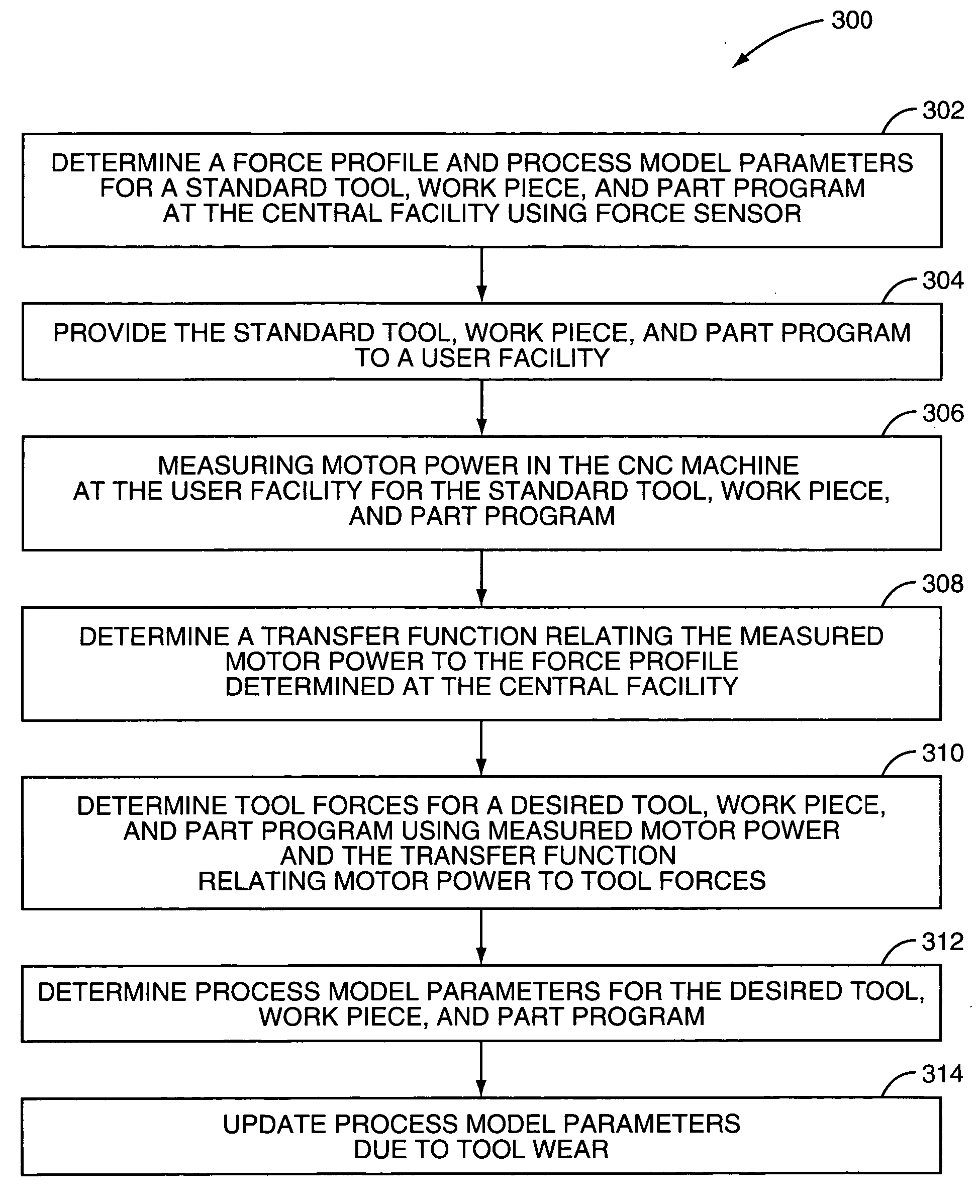
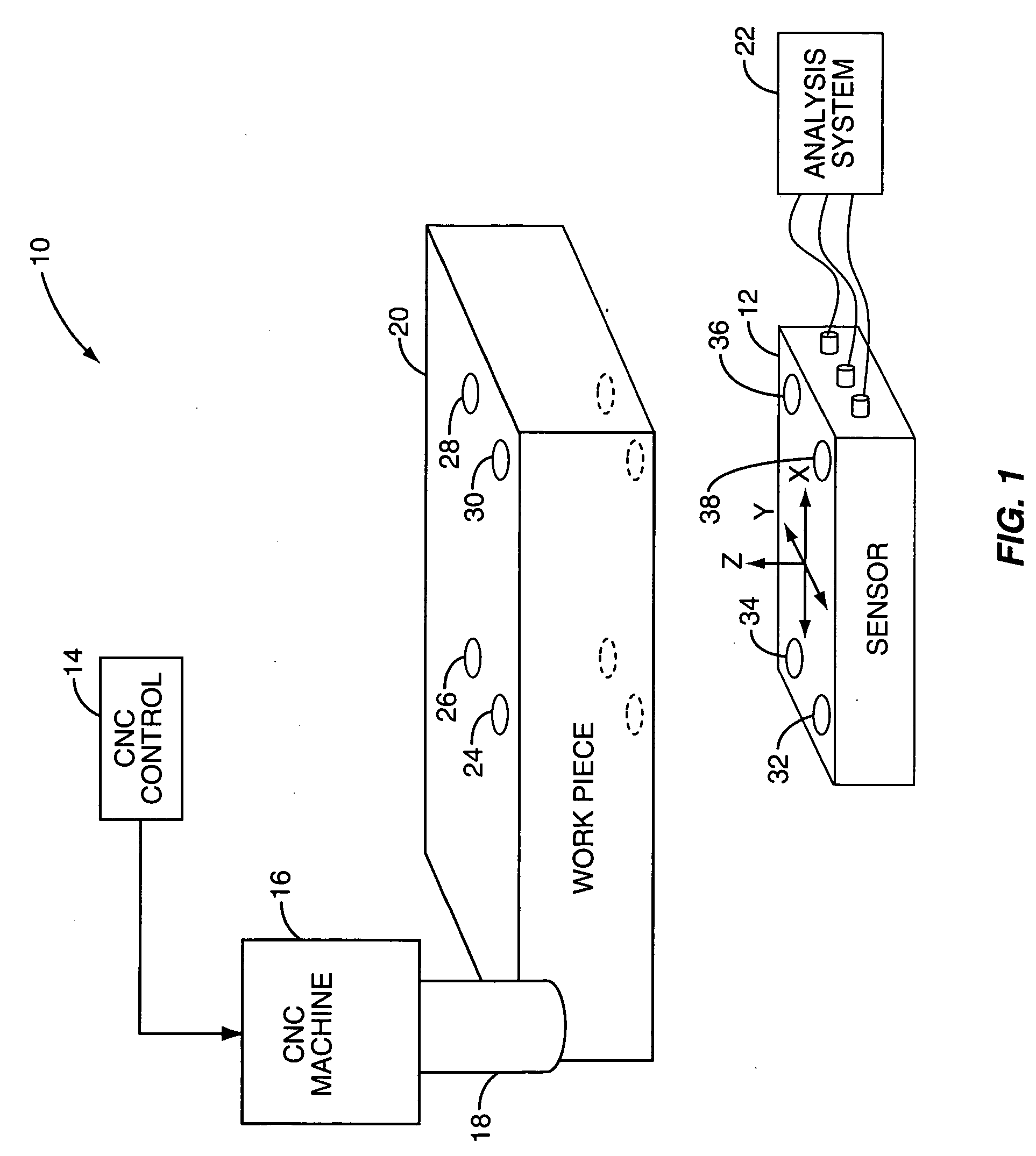
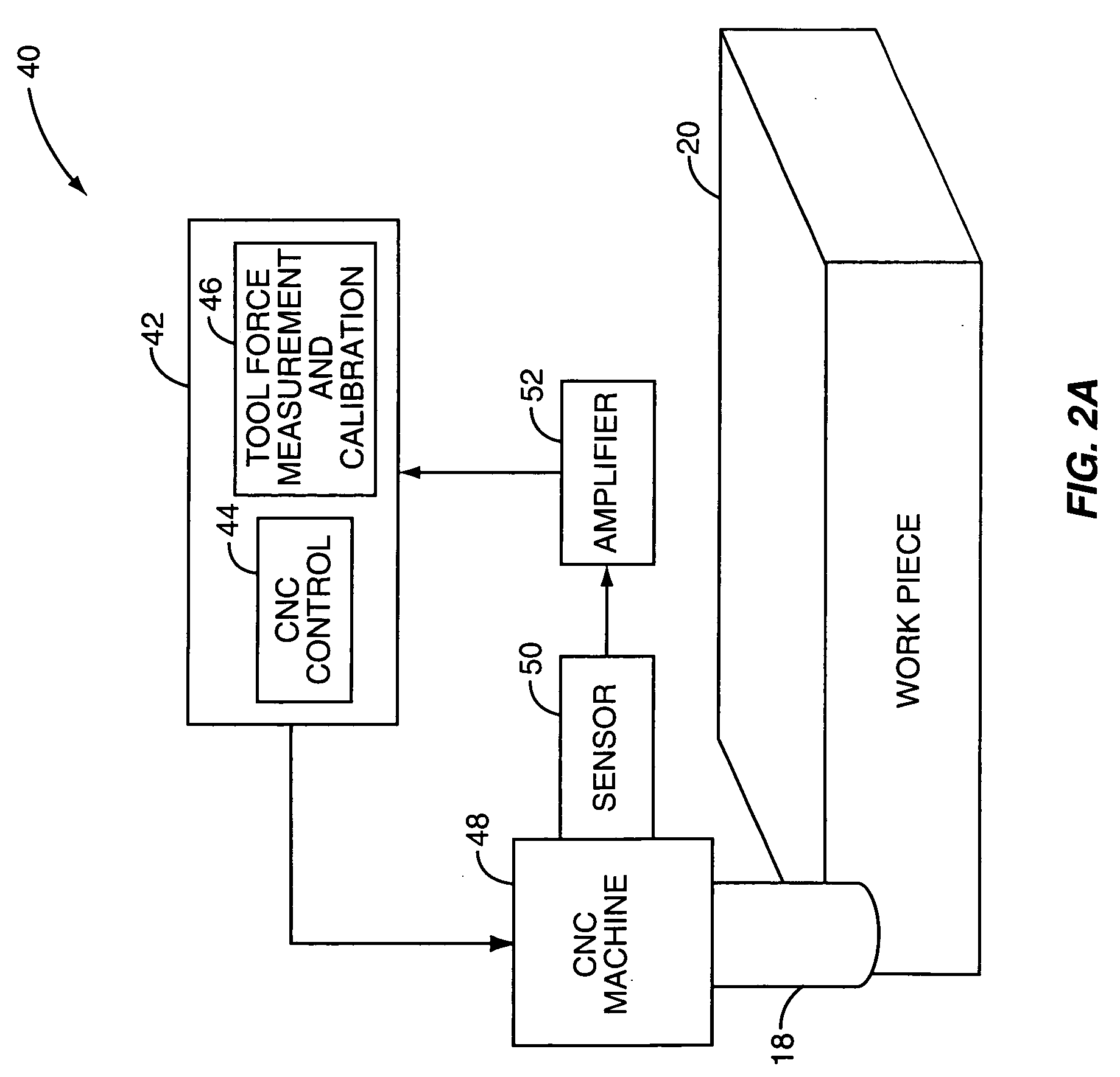
[0019] The present invention provides a system for measuring tool forces and process model parameters in real-time without the use of force sensors that directly sense tool forces. The force sensors are expensive and, due to their compliance, make the Computer Numerical Control (CNC) machine less stiff and degrade its performance. Indirect sensors, such as power sensors, are inexpensive and non-invasive. However, the difficulty ...


PUM


Abstract

A system and method are provided for real-time measurement of tool forces. A relationship between a motor characteristic and tool forces is determined by first directly measuring tool forces for a standard tool, work piece, and part program in a central facility. A force profile indicative of the tool forces and the standard tool, work piece, and part program are provided to a user at a user facility. The motor characteristic for a CNC machine at the user facility is then measured for the standard tool, work piece, and part program. Based on the force profile determined at the central facility, the relationship between the motor characteristic and tool forces is determined. Thereafter, the motor characteristic of the CNC machine is measured for a desired tool, work piece, and part program and converted to tool forces using the relationship between the motor characteristic and tool forces.

Description

RELATED APPLICATIONS [0001] The present application claims priority from provisional U.S. patent application Ser. No. 60 / 534,995, entitled DEVICE FOR ACTIVELY MONITORING THE CONDITION OF A TOOL IN A CNC MACHINE, filed Jan. 9, 2004 and provisional U.S. patent application Ser. No. 60 / 537,561, entitled METHOD FOR REAL-TIME MEASUREMENT OF TOOL FORCES AND MACHINING PROCESS MODEL PARAMETERS, filed Jan. 21, 2004, both of which are hereby incorporated herein by reference in their entireties.FIELD OF THE INVENTION [0002] The present invention relates to Computer Numerical Control (CNC) machining, and more particularly relates to a method for real-time measurement of tool forces and machining process model parameters. BACKGROUND OF THE INVENTION [0003] Tool forces depend on the particular tool, cutting geometry, stock (work piece), and other cutting conditions including whether or not coolant is used. Current methods for measuring tool forces require the use of a complex and expensive dedicat...

Claims


Application Information

Patent Timeline
IPC IPC(8): G06F19/00
CPCG05B19/4065
Inventor ESTERLING, DONALD M.
Owner UNIVERSITY OF NEW HAMPSHIRE
Why Eureka
Try Eureka