Method of determining elastic modulus

a technology of elastic modulus and modulus, applied in the direction of mechanical measuring arrangement, force/torque/work measurement apparatus, instruments, etc., can solve problems such as difficult to be determined accurately, signal-to-noise ratio, and possible introduction of errors

Inactive Publication Date: 2005-07-14
THE HONG KONG POLYTECHNIC UNIV
View PDF1 Cites 35 Cited by
  • Summary
  • Abstract
  • Description
  • Claims
  • Application Information

AI Technical Summary

Benefits of technology

[0006] Therefore, it is an object of this invention to reduce at least one or more of the problems as set forth in the prior art. As a minimum, it is an object of this invention to provide the public with a useful choice.

Problems solved by technology

As such, errors could be introduced, especially when “piling-up” of the indented material at the point of contact occurs.
Moreover, the initial unloading slope Su of the unloading curve is needed, but it is sometimes difficult to be determined accurately, especially in the cases where the signal-to-noise ratio is low.
Compared with the slope method, this method does not require A(hc), but it still relies on the use of the initial unloading slope, which may be the major source of error.
Further, in Cheng et. al. paper, the indenter is assumed to be ideally sharp, so that the treatment is not detailed enough for the model to be practically useful, but more work has to be done to take the indenter bluntness effects into consideration.

Method used


Image

  • Method of determining elastic modulus
  • Method of determining elastic modulus
  • Method of determining elastic modulus

Examples


examples

Experimental Verification of the Method

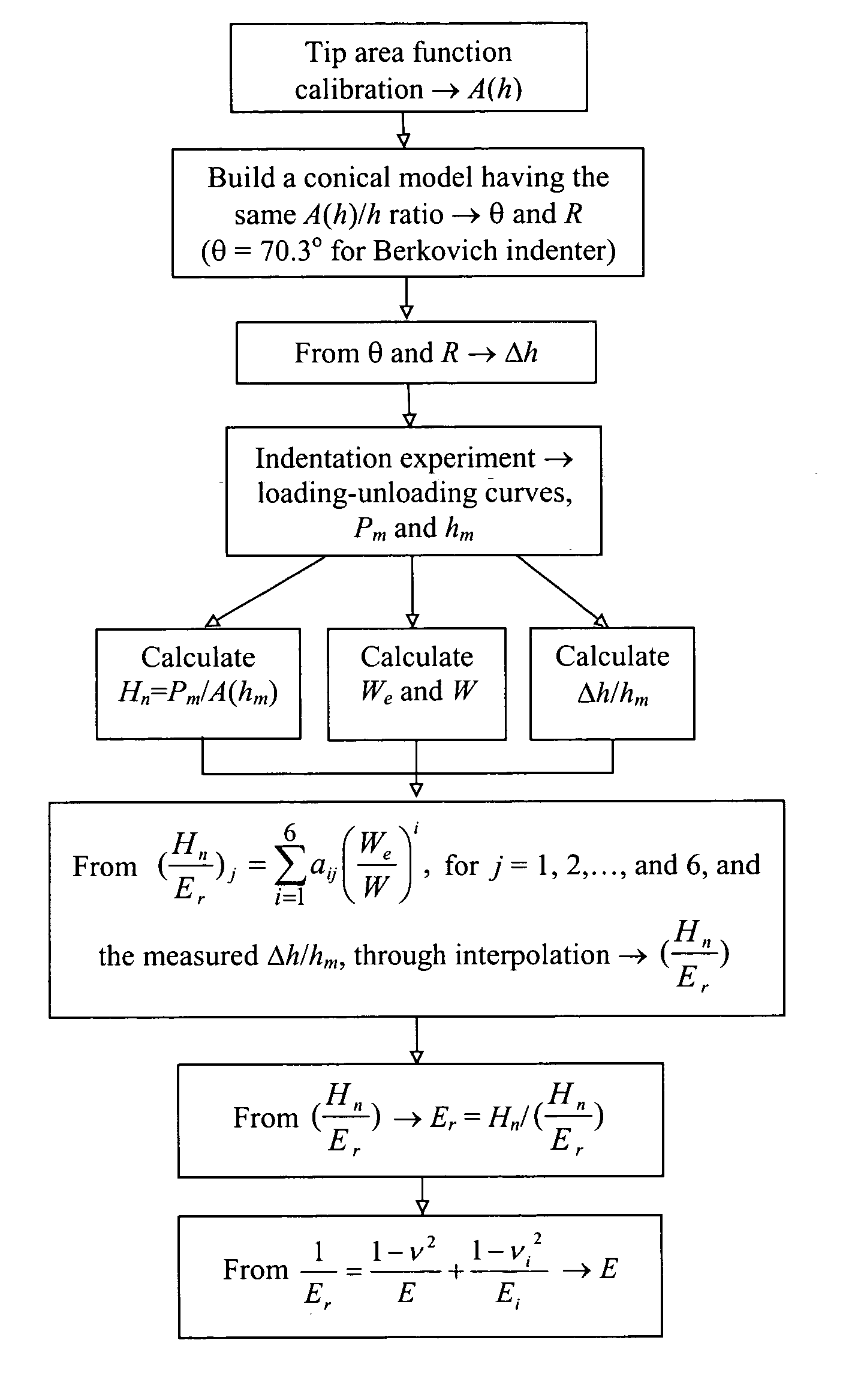
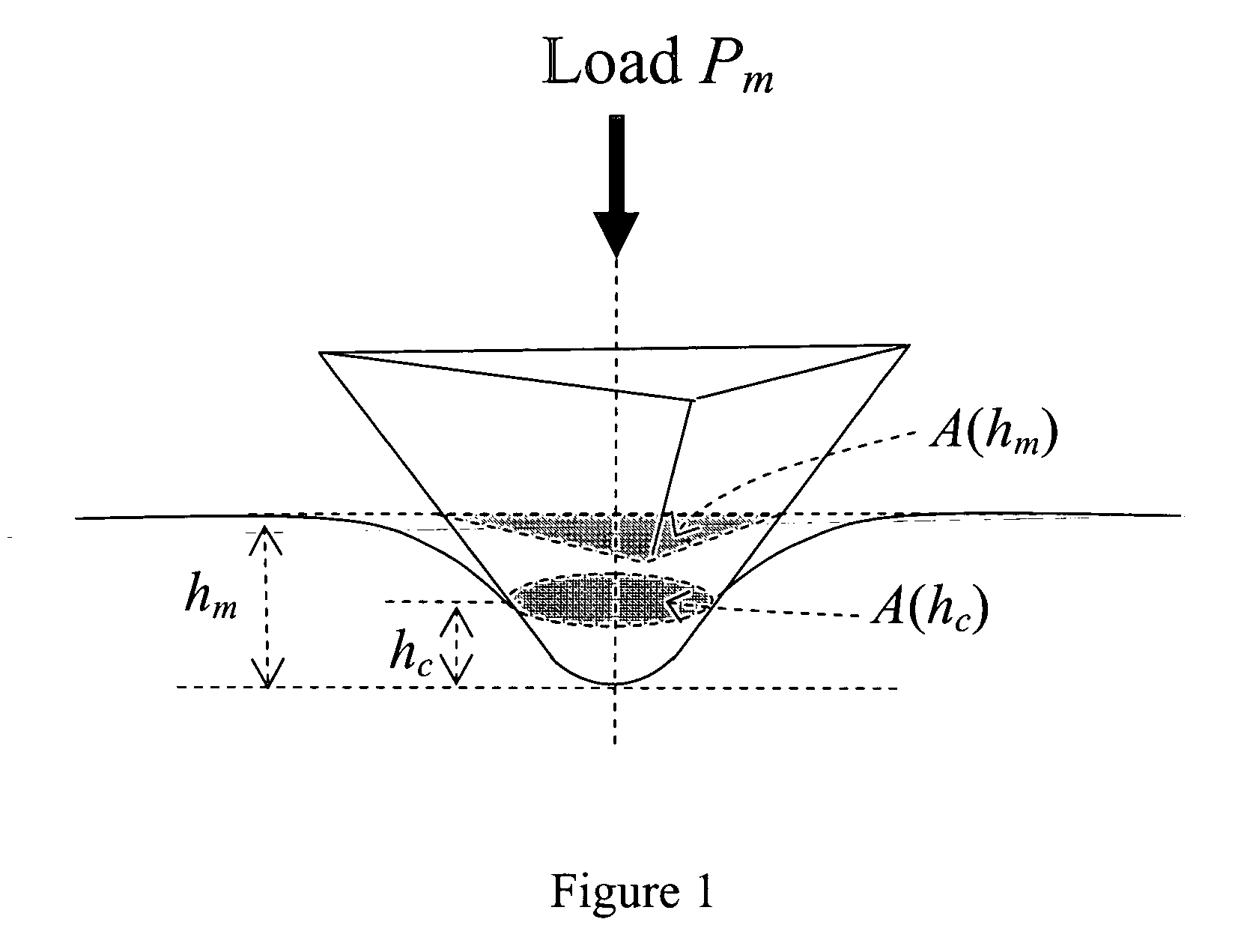
[0047] The validity of the method was examined through indentation tests made on five materials, i.e. S45C carbon steel, 6061 aluminum alloy, tungsten single crystal, aluminum single crystal and fused silica. The surfaces of these samples were polished to mirror finish. A Nanoindenter IIs (Nano instruments inc.) equipped with a diamond Berkovich indenter with certain bluntness was used to perform the experiments. The real tip area function was calibrated first. The Berkovich indenter used in this exemplary demonstration is modeled with a conical indenter shape with a half-included angle θ of 70.3 degree and a spherical cap with a radius of R=650 nm. To show the equivalency between the real indenter tip and the non-ideal conical model, the calibrated area function A(h) of the former is converted into a radius function r(h)≡[A(h) / π]0.5, which is in good agreement with the radius of the conical model at all depth h. The absolute bluntness is thu...


PUM

PropertyMeasurementUnit
half-included angleaaaaaaaaaa
Poisson's ratiosaaaaaaaaaa
elastic modulusaaaaaaaaaa

Abstract

Errors in current methods of determining elastic modulus through depth-sensing indentation may be resulted from three major factors: 1. error in estimating the projected contact area A(hc) by indirect means such as from the unloading curve, especially in the cases where “piling-up” occurs; 2. reliance on the use of the initial unloading slope Su, which in some cases is not easily determined reliably; and 3. insufficient consideration on the influences due to indenter bluntness in some important models based on numerical treatments. This invention provides a new method of determining elastic modulus of an indented material, which overcomes the above deficiencies. The maximum load and the total displacement of the indenter (to give a nominal hardness defined in this invention), elastic work and total work are measured. From these data, the reduced elastic modulus is thus determined through a set of function-like relationships established in this invention, which is then used to calculate the elastic modulus of the indented material.

Description

FIELD OF THE INVENTION [0001] This invention relates to a method for determining elastic modulus, particularly by indentation techniques. BACKGROUND OF THE INVENTION [0002] Elastic modulus plays a central role in the understanding of the mechanical behavior of a material. in practice, there is a need to determine the elastic modulus of materials on small scales. in the past decade, depth-sensing indentation technique has become a very useful tool for this purpose, particularly in determining the mechanical properties of materials on small scales by recording the load v.s. displacement of the indenter during indentation (loading and unloading curves), from which the mechanical properties of the indented material are estimated. [0003] Oliver and Pharr (J. Mater. Res. 7, 1564, (1992)) proposed a classic formula correlating the reduced elastic modulus (Er), the initial slope of the unloading curve Su, and the projected contact area A(hc) at the maximum indentation load: Er=π2⁢ ⁢β⁢(SuA⁡...

Claims


Application Information

Patent Timeline
Patent Type & Authority Applications(United States)
IPC IPC(8): G01N3/00G01N3/02G01N3/42G06F19/00
CPCG01N3/42G01N2203/0212G01N2203/008G01N2203/0075
Inventor MA, DEJUNONG, CHUNG-WO
Owner THE HONG KONG POLYTECHNIC UNIV
Why Eureka
Try Eureka