Radio frequency identification simulator and tester

a radio frequency identification and simulator technology, applied in the field of radio frequency identification simulator and tester, can solve the problems of not actively managing the database of rfid system component specifications, time-consuming and costly process, and facing challenges imposed

Inactive Publication Date: 2005-07-14
QUAKE GLOBAL
View PDF20 Cites 56 Cited by
  • Summary
  • Abstract
  • Description
  • Claims
  • Application Information

AI Technical Summary

Problems solved by technology

RFID systems may identify objects at greater distances than optical systems, may store information into read / write tags, may operate unattended, and may read tags hidden from visual inspection for security purposes.
As organizations strive to adopt RFID systems for tracking objects, they face challenges imposed by the nature of the objects they handle and the environments in which those objects are processed.
Often companies must purchase and evaluate systems through trial and error, a time-consuming and costly process.
The apparatus does not actively manage a database of RFID system component specifications, does not perform constraint analysis, and does not simulate RFID system use.
The apparatus does not populate a database of RFID system component specifications, does not perform constraint analysis based on parameters such as cost, object velocity, or environmental materials, and does not simulate RFID system use.
The system does not provide information regarding the placement of radio frequency transceivers with respect to each other, does not simulate radio wave propagation, and does not simulate RFID system use.

Method used


Image

  • Radio frequency identification simulator and tester
  • Radio frequency identification simulator and tester
  • Radio frequency identification simulator and tester

Examples


Embodiment Construction

[0032] The following detailed description of preferred embodiments of this invention and the attached figures are intended to provide a clear description of the invention without limiting its scope.

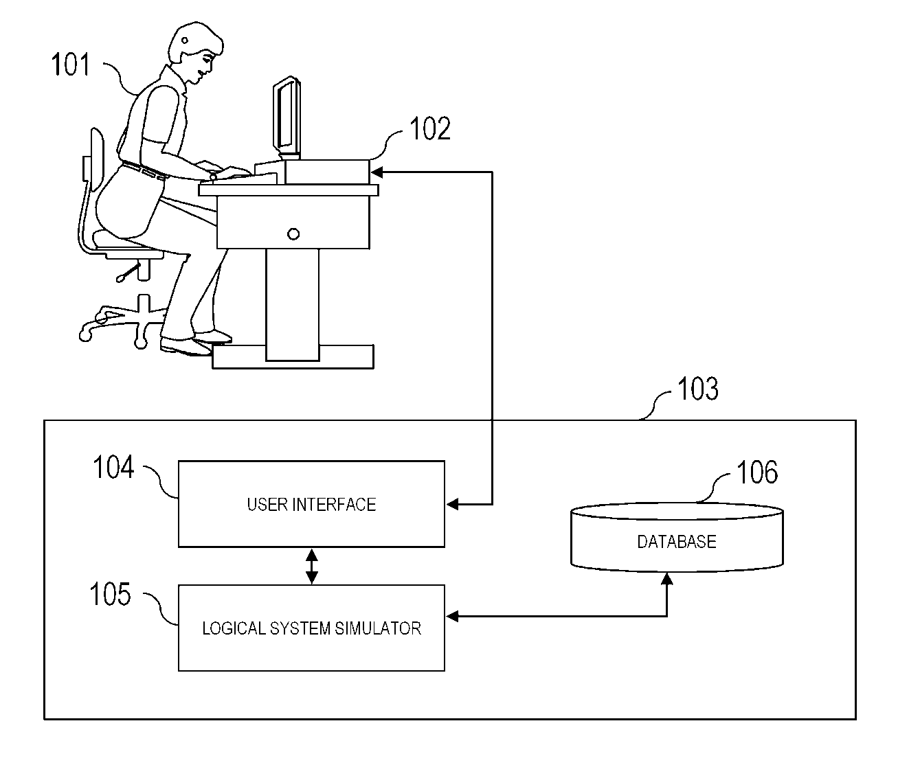
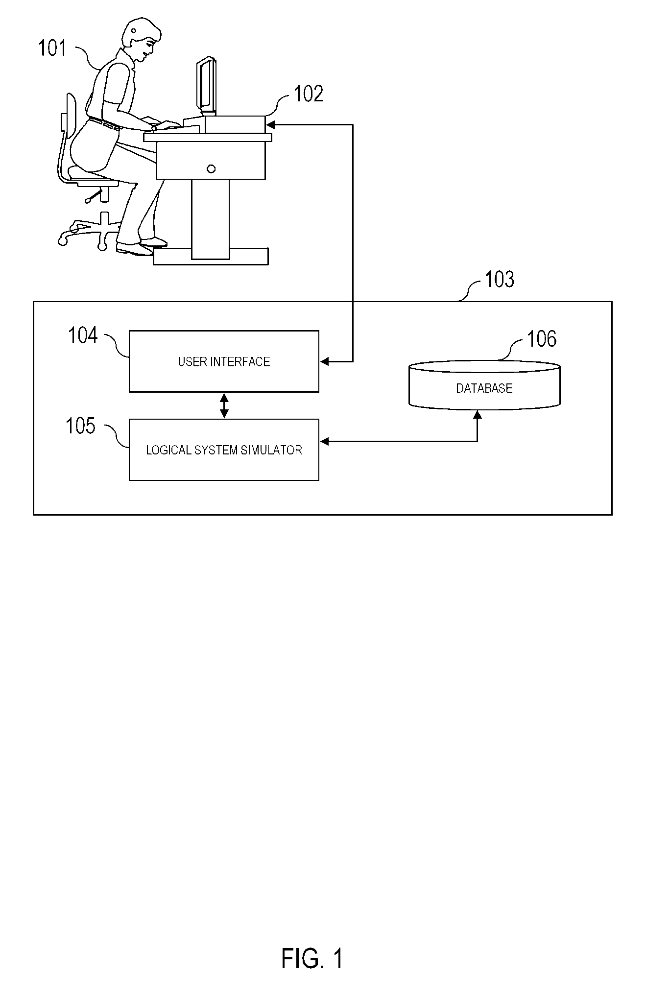
[0033]FIG. 1 is a diagram illustrating the overall structure of an embodiment of the system. A user of the system 101 accesses a computer with graphical display 102. The system 103 operates primarily upon the hardware of computer 102 and consists of several major components. The user interface 104 allows for the user 101 to input information and view or otherwise output results. The logical system simulator 105 uses the information gathered from the user interface 104, radio wave propagation simulator 106, database 107, data network 108, and RFID interrogator 112. The data network 109 is accessible by peers of the system 110 and 111. Information from RFID interrogator 112 confirms or invalidates information presented by other sources based on the RF tags that it reads within the actual e...


PUM


Abstract

A method and system for simulating radio frequency identification (RFID) systems. The system determines RFID system configurations and components that meet user constraints to facilitate planning for RFID system deployment. The simulator updates a database on the basis user input and radio frequency interrogator data from deployed systems.

Description

[0001] This application is a Continuation of application Ser. No. 10 / 707,820, filed Jan. 14, 2004, entitled, “Radio frequency identification simulator”, which application is incorporated herein by reference.”BACKGROUND OF INVENTION [0002] Radio frequency identification (RFID) systems allow for the identification of objects at a distance and out of line of sight. They are comprised of transponders called radio frequency (RF) tags and RF interrogators (also called readers). The tags are generally smaller and less expensive than interrogators, and are commonly attached to objects such as product packages in stores. When an interrogator comes within range of an RF tag, it may provide power to the tag via a querying signal, or the RF tag may use stored power from a battery or capacitor to send a radio frequency signal to be read by the RFID interrogator. [0003] RF tags may consist of single integrated circuits, circuits and antennas, or may incorporate more complex capabilities such as c...

Claims


Application Information

Patent Timeline
Patent Type & Authority Applications(United States)
IPC IPC(8): G06F17/50G06K17/00
CPCG06K17/0022G06F30/20
Inventor SWEENEY, PATRICK JOSEPH II
Owner QUAKE GLOBAL
Why Eureka
Try Eureka