
Steering wheel damper

Inactive Publication Date: 2005-07-21
AUTOLIV ASP INC
View PDF25 Cites 9 Cited by
  • Summary
  • Abstract
  • Description
  • Claims
  • Application Information

AI Technical Summary

Benefits of technology

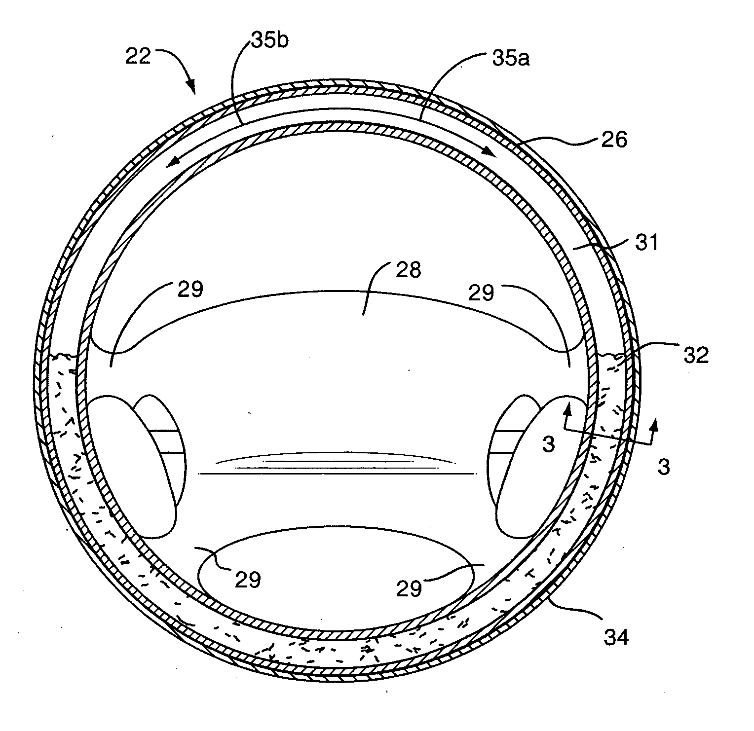
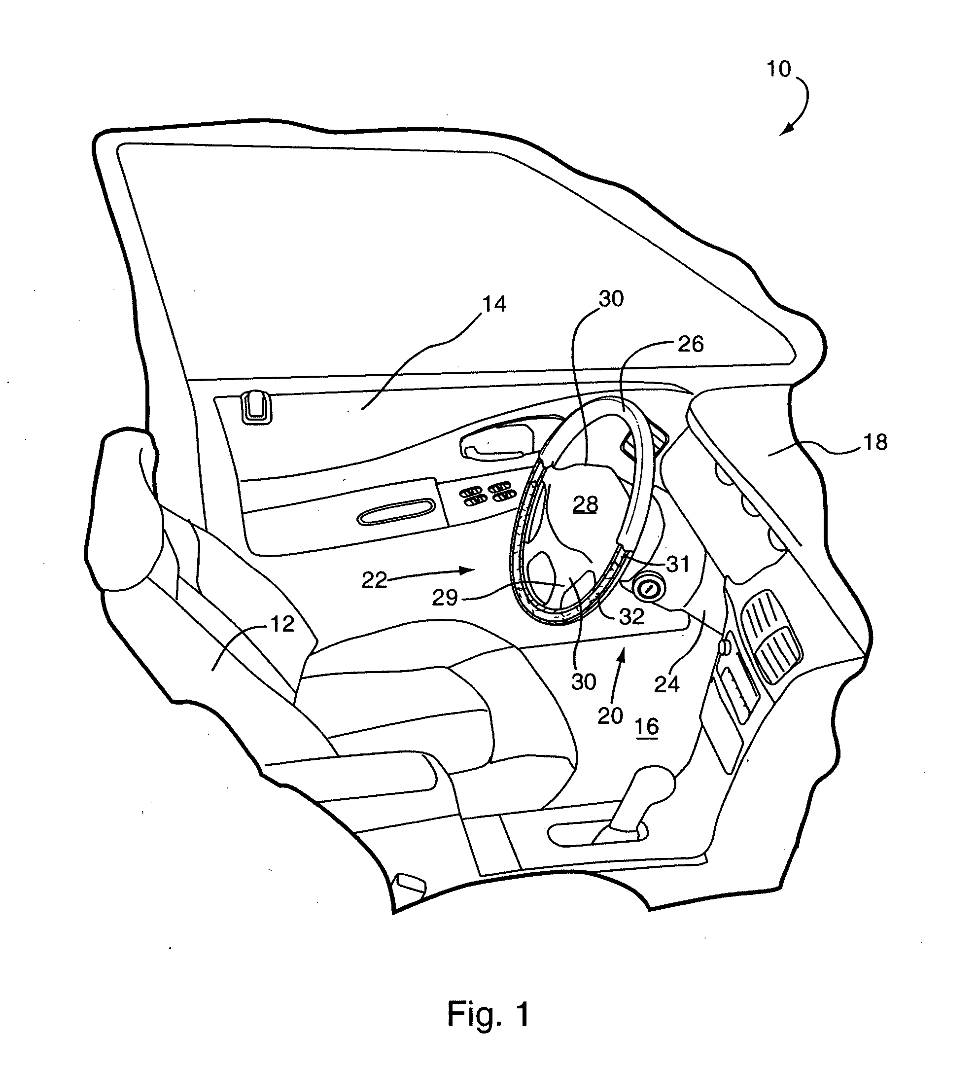
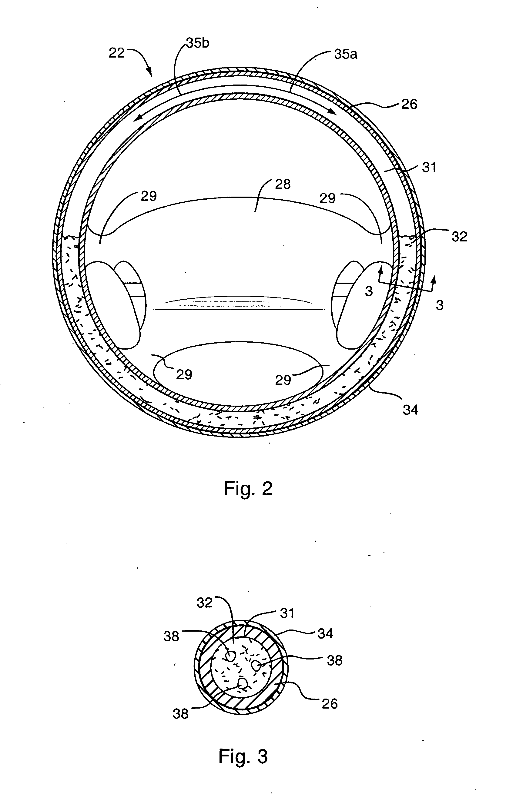
[0015] The present invention has been developed in response to the present state of the art, and, in particular, in response to problems and needs in the art that have not yet been fully solved by currently available steering wheel dampers. More specifically, the present invention provides a cost-effective system for damping vibrations in the steering wheel of a vehicle by placing a damping fluid in the outer rim of the steering wheel. The present invention also provides a convenient technique for adjusting the weight and thus the inertia of the steering wheel, which facilitates smooth operation of the vehicle.
[0021] The volume, viscosity, and weight of the fluid are selected to dampen vibrations of the outer rim and / or provide a predetermined inertia for the outer rim. In certain embodiments, the volume of the fluid is less than the entire volume of the internal chamber. For example, the volume of the fluid may be about half of the entire volume of the internal chamber.
[0025] The viscosity of the fluid also affects the inertia of the steering wheel. A fluid that is too viscous may make it difficult to change the direction of the steering wheel, while a fluid of insufficient viscosity will not provide adequate resistance to rotation of the wheel to enable smooth operation of the vehicle. Accordingly, the fluid within the outer rim may be selected to provide a predetermined inertia for the outer rim. Through altering the volume and type of the fluid within the steering wheel, the present invention provides a simple, cost-effective technique for changing the inertia of the steering wheel.
[0029] In view of the foregoing, the steering wheel of the present invention provides substantial advantages over conventional damping systems. The present invention is easy to implement and is cost-effective. Furthermore, the volume and type of fluid in the outer rim may be easily adjusted to adapt to the vibrational characteristics of a particular vehicle. Furthermore, the inertia of the steering wheel may be set to a desired level by adjusting the volume and type a fluid present in the outer rim. The present invention is also compact and takes advantage of a space in the vehicle that was previously unused.

Problems solved by technology

The movement of these components produces vibrations, which can be transferred throughout the vehicle.
The engine, for example, can be a source of significant vehicle vibrations.
Unfortunately, these alterations may adversely affect fuel economy or the performance of the vehicle.
An additional source of vehicle vibration is contact between the vehicle and the driving surface.
For example, vehicle speed, aberrations in the driving surface, wheel alignment, and uneven tire wear can significantly impact the vibrations generated in the vehicle.
Nevertheless, problems still persist and vibration control is an ongoing concern for automobile manufacturers.
When the frequency of the generated vibrations substantially matches the natural resonance frequency of a part of the vehicle, that part vibrates and may cause adjoining or abutting parts to also vibrate.
Such vibrations can cause annoyance to the driver and even premature part failure.
However, these alterations may be expensive and can adversely affect the performance of the vehicle.
It has been shown that even a slight vibration in the steering wheel can cause driver fatigue and discomfort.
Steering wheel vibrations can also affect a driver's decision to purchase a vehicle.
These vibrations may cause a potential purchaser to believe that the vehicle is not operating properly, or that the vehicle is of inferior quality.
Unfortunately, these damping systems often require additional space and significant design alterations to the steering wheel.
Moreover, they are often inconsistent with the aesthetic or functional scheme of the vehicle.
Unfortunately, these components have a limited damping effect, and can require significant and costly modifications to the steering assembly.
These complex damping systems are, unfortunately, expensive and require extensive modifications of the vehicle for installation.
Moreover, they often involve a complex set of interconnected moving parts, which are subject to wear and tear and increase the likelihood of product failure.

Method used


Image

  • Steering wheel damper
  • Steering wheel damper
  • Steering wheel damper

Examples


Embodiment Construction

[0037] The preferred embodiments of the invention are now described with reference to FIGS. 1-5, wherein like parts are designated by like numerals throughout. The members of the present invention, as generally described and illustrated in the Figures, may be constructed in a wide variety of configurations. Thus, the following more detailed description of the embodiments of the present invention, as represented in the Figures, is not intended to limit the scope of the invention, as claimed, but is merely representative of presently preferred embodiments of the invention.

[0038] In this application, the phrases “connected to,”“coupled to,” and “in communication with” refer to any form of interaction between two or more entities, including mechanical, electrical, magnetic, electromagnetic, electromechanical and thermal interaction. The phrase “attached to” refers to a form of mechanical coupling that restricts relative translation or rotation between the attached objects. The phrases ...


PUM


Abstract

A steering wheel having a central member and an outer rim connected to the central member is disclosed. The central member is attachable to a steering column of a vehicle. The outer rim has one or more internal chambers. A fluid, such as antifreeze, is disposed within the internal chamber or chambers. The volume, viscosity, and weight of the fluid is selected to dampen vibrations of the steering wheel caused by operation of the vehicle and / or to achieve a desired inertia level in the steering wheel.

Description

BACKGROUND OF THE INVENTION [0001] 1. Field of the Invention [0002] The present invention relates to steering wheel systems for motor vehicles. More specifically, the invention relates to the addition of fluid to the interior of a steering wheel to dampen vibration and increase the inertia of the steering wheel. [0003] 2. Description of Related Art [0004] Motor vehicles involve components which rotate, oscillate, and move in various directions. The movement of these components produces vibrations, which can be transferred throughout the vehicle. The engine, for example, can be a source of significant vehicle vibrations. The vibrations of the engine may be minimized by altering the RPMs (revolutions per minute) of the engine. Unfortunately, these alterations may adversely affect fuel economy or the performance of the vehicle. [0005] An additional source of vehicle vibration is contact between the vehicle and the driving surface. A number of variables affect the vibrations generated b...

Claims


Application Information

Patent Timeline
IPC IPC(8): B62D1/06B62D7/22
CPCB62D1/06Y10T74/20834B62D7/222
Inventor BIRCHMEIER, GREGPALM, DAVID JR.
Owner AUTOLIV ASP INC
Learn More