Dielectric waveguide filter
a filter and waveguide technology, applied in the direction of waveguides, electrical devices, coupling devices, etc., can solve the problems of high degree of performance variability, low yield, and tendency to misregister between the via-hole and the conductive pattern
- Summary
- Abstract
- Description
- Claims
- Application Information
AI Technical Summary
Benefits of technology
Problems solved by technology
Method used
Image
Examples
first embodiment
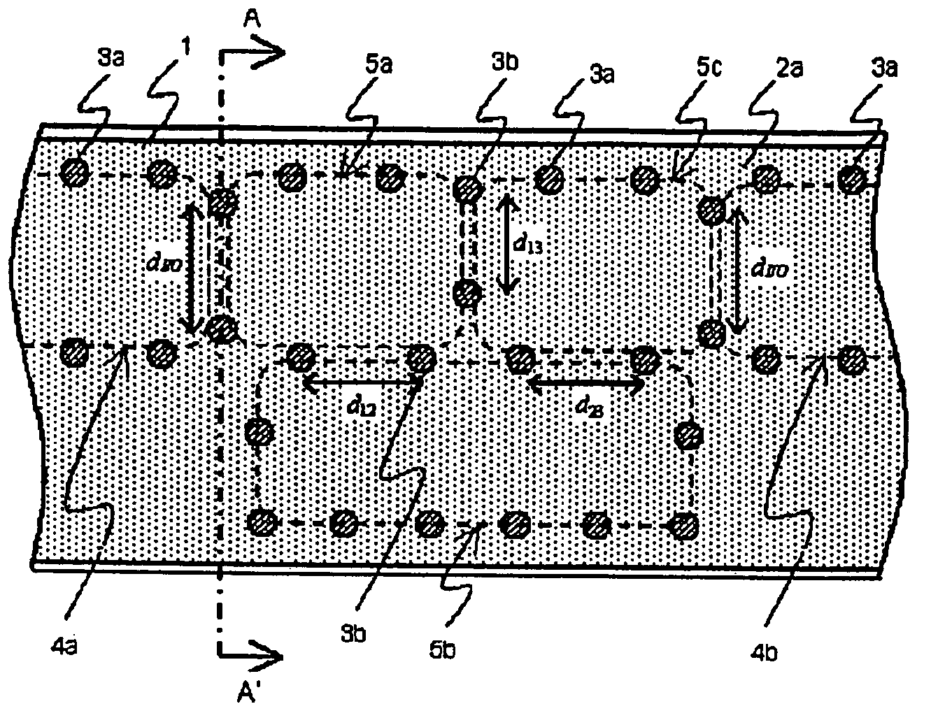
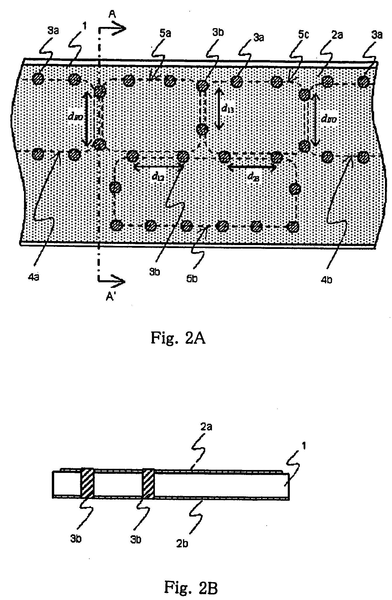
[0024] A first embodiment according to the present invention will now be explained in detail with reference to FIG. 2. FIG. 2A is a plan view of a filter substrate, and FIG. 2B is a sectional view taken along alternate long and short dash line A-A′ in FIG. 2A.
[0025] Upper and lower conductive layers 2a and 2b are formed on the upper and lower surfaces of dielectric substrate 1. Upper and lower conductive layers 2a and 2b are connected each other by via-hole rows 3a and 3b that are formed with a spacing being equal to or less than ½ of the wavelength in the dielectric substrate at the resonance frequency, whereby first-stage, second-stage, and third-stage dielectric resonators 5a, 5b, and 5c and input / output waveguide structures 4a and 4b are formed. The filter is configured such that first-stage resonator 5a and second-stage resonator 5b are coupled by an electromagnetic field by means of dielectric windows in the form of via-holes 3b with a spacing being equal to d12 and second-sta...
second embodiment
[0026] As the present invention, a configuration that allows regulation of the filter characteristics will be explained with reference to FIG. 3. FIG. 3A is a plan view of the filter substrate, FIG. 3B is a detailed view of the area 6 enclosed by the dotted lines in FIG. 3A, and FIG. 3C is a sectional view taken along alternate long and short dash line B-B′ in FIG. 3B.
[0027] Forming slot 7 around the periphery of via-hole 3a that forms a resonator causes pad 8 to be formed that is electrically isolated from conductive layer 2a. This pad 8 and conductive layer 2a are connected each other by, for example, bonding wires 9. The number of wires or their length are regulated to form inductance regulator 6 for regulating the inductance of via-holes 3a that form the side walls of the dielectric resonator. Changes in the inductance change the resonance frequency of the dielectric resonator. Accordingly, forming inductance regulator 6 in each resonator stage enables regulation of the center f...
third embodiment
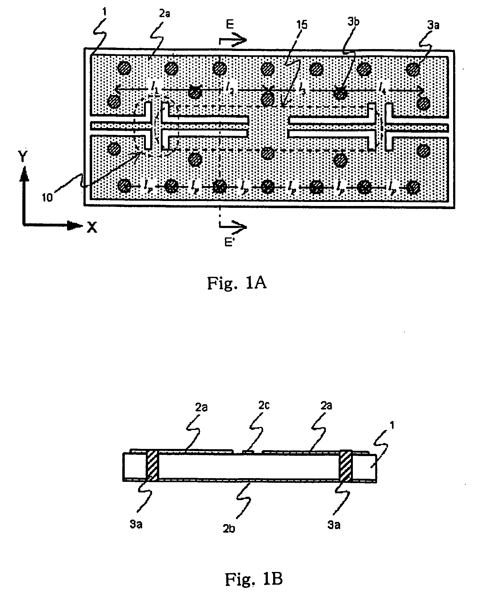
[0028] the present invention will now be explained in detail with reference to FIG. 4. FIG. 4A is a plan view of the filter substrate, and FIG. 4B is a sectional view taken along alternate long and short dash line C-C′ in FIG. 4A.
[0029] Upper and lower conductive layer 2a and 2b are formed on the surfaces of dielectric substrate 1. First-stage, second-stage, and third-stage dielectric resonators 5a, 5b, and 5c are formed by connecting these upper and lower conductive layers 2a and 2b by means of via-hole rows 3a and 3b that are formed with a spacing being equal to or less than ½ of the wavelength in the dielectric substrate at the resonance frequency. Formed on first-stage resonator 5a and third-stage resonator 5c are waveguide-coplanar converters 10 that are connected to input / output coplanar lines that are made up of ground conductive layer 2a and signal conductive layer 2c. The degree of electromagnetic field coupling between input / output stage resonators 5a and 5c and waveguide-...
PUM
 Abstract
Description
Claims
Application Information
 - R&D
- Intellectual Property
- Life Sciences
- Materials
- Tech Scout
- Unparalleled Data Quality
- Higher Quality Content
- 60% Fewer Hallucinations
Browse by: Latest US Patents, China's latest patents, Technical Efficacy Thesaurus, Application Domain, Technology Topic, Popular Technical Reports.
© 2025 PatSnap. All rights reserved.Legal|Privacy policy|Modern Slavery Act Transparency Statement|Sitemap|About US| Contact US: help@patsnap.com


