Scanning interferometer for aspheric surfaces and wavefronts

an interferometer and aspheric surface technology, applied in the field of interferometry, can solve the problems of difficult measurement of aspheric surfaces and wavefronts, rare and expensive materials, and inability to test the fundamental single lens element with either spherical or aspheric surfaces properly

Inactive Publication Date: 2005-07-21
ZYGO CORPORATION
View PDF13 Cites 49 Cited by
  • Summary
  • Abstract
  • Description
  • Claims
  • Application Information

AI Technical Summary

Benefits of technology

[0036] According to another aspect of the invention, a test-set up is calibrated absolutely by measuring an aspherical surface of known shape in the same way as an unknown aspherical surface would be probed, i.e., by scanning axially. This known surface could be a parabola, for instance, which can be measured absolutely with the help of a known plane mirror and a known spherical mirror using known procedures available to measure those surfaces in an absolute manner. Another possibility is to use a lens with spherical surfaces used i...

Problems solved by technology

In addition, lens surfaces in multi-element lithography lenses operating at wavelengths of 193 nm and 157 nm are made aspherical to lower the number of elements made, which are of rare and expensive materials.
So even the fundamental single lens element with either spherical or aspherical surfaces can only be tested properly if one is able to deal with aspherical wavefronts in a test set-up.
The measurement of aspherical surfaces and wavefronts has been very difficult because of the large departure from the best fitting sphere.
But, it is obvious that the same difficulties exist for this type of testing because, again, an aspherical wavefront is produced.
Nevertheless, the final accuracy is questionable because of accumulation of measurement errors and the uncertainty of the homogeneity within the lens, material.
While these techniques have utility for many applications, they are limited in their operational capabilities or precision compared with those needed for today's evolving lithography applications.
Contacting and non-contacting stylus based profilers mechanically scan the aspherical surface under test and, therefore, are slow because they measure only a few data points at a time.
Slow techniques are very susceptible to measurement errors due to temperature variations during the measurement.
The same limitations apply to contacting and...

Method used


Image

  • Scanning interferometer for aspheric surfaces and wavefronts
  • Scanning interferometer for aspheric surfaces and wavefronts
  • Scanning interferometer for aspheric surfaces and wavefronts

Examples


Embodiment Construction

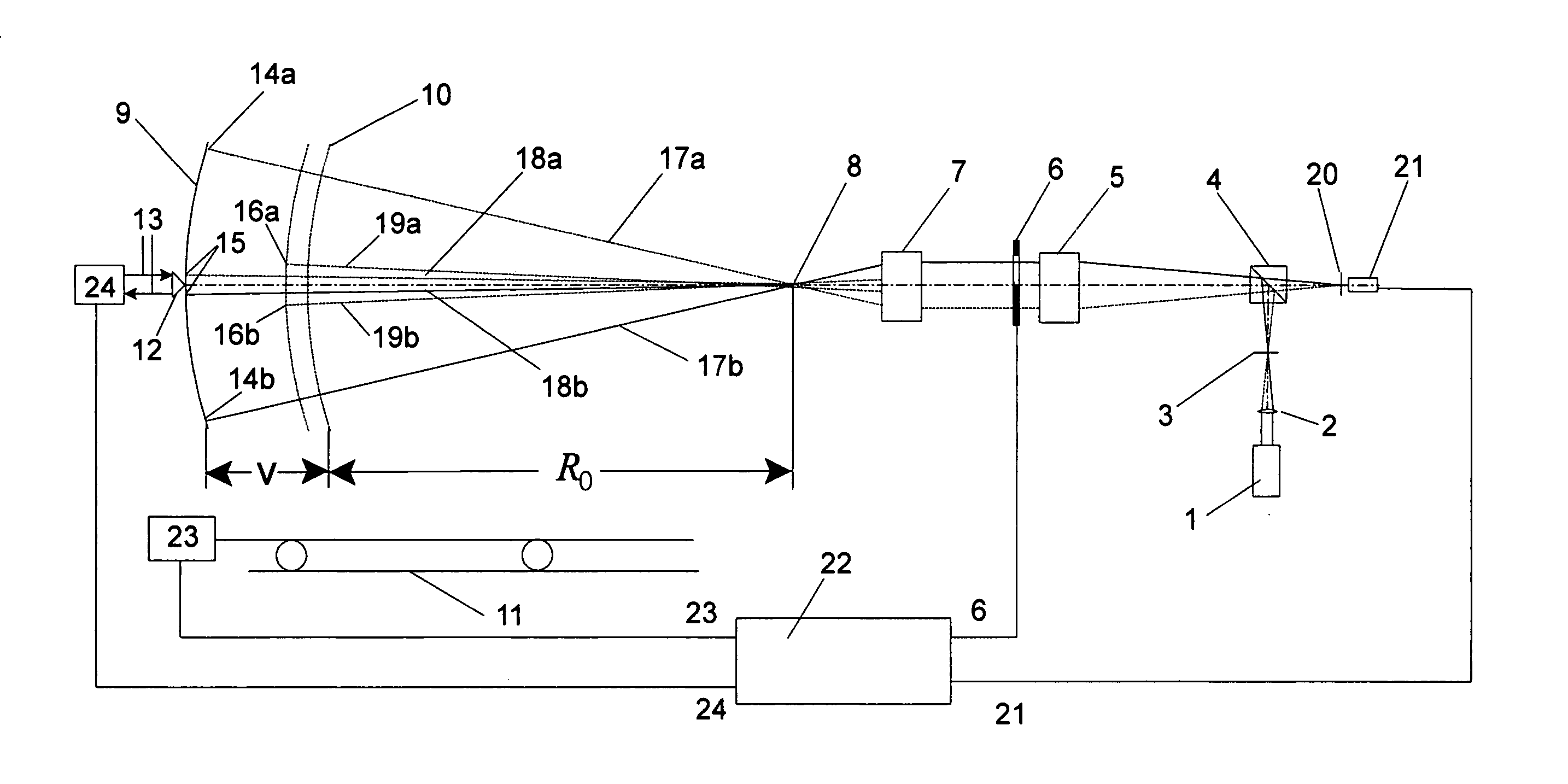
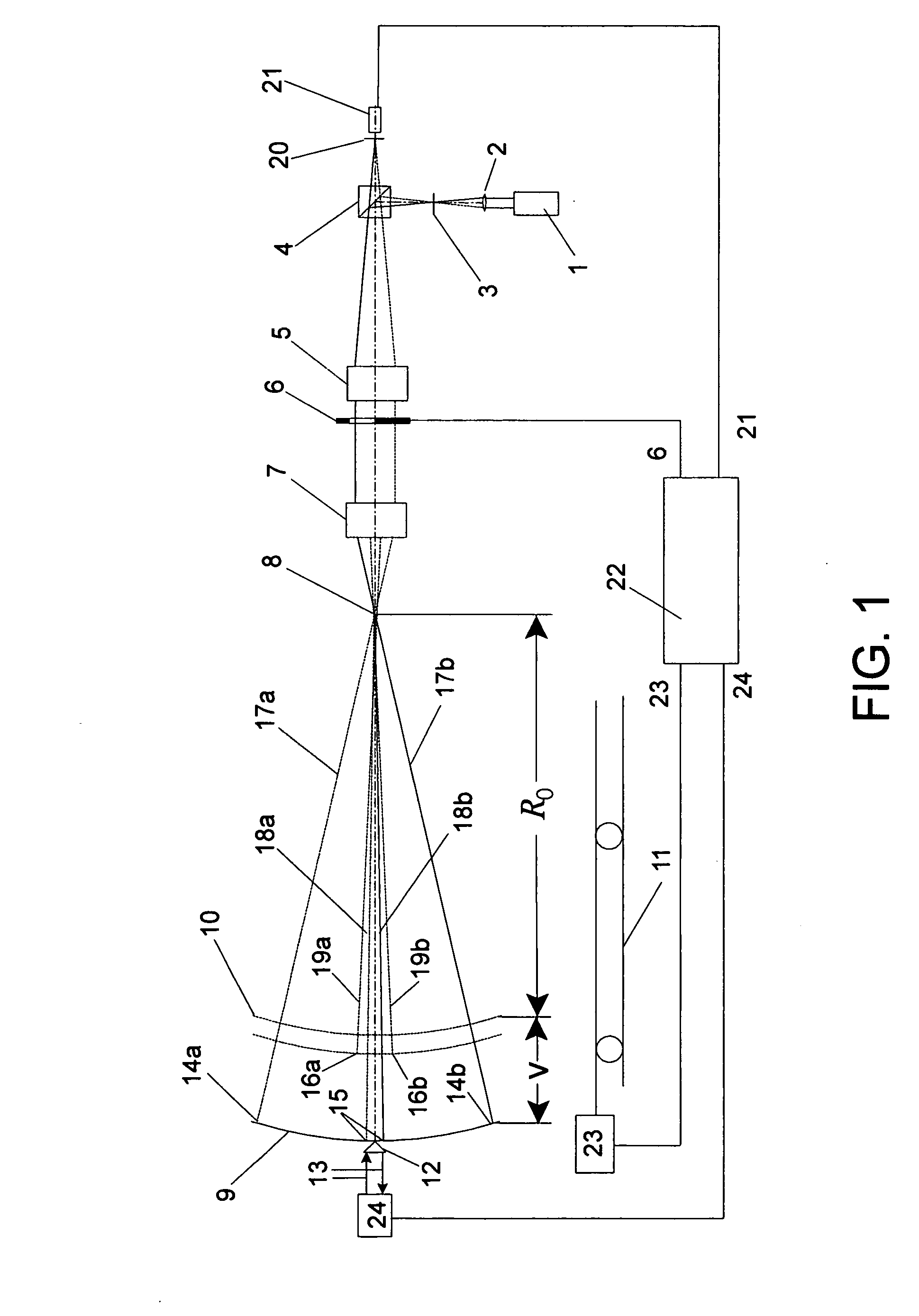
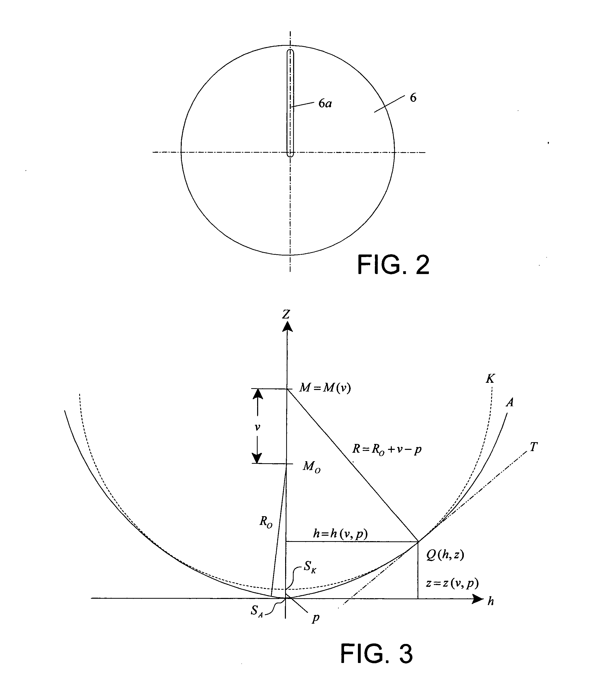
[0069] The preferred embodiments together with a associated algorithms will now be described in a more detailed manner. Reference now made to FIG. 1 that shows a simple embodiment of the invention. Light from a coherent light source 1 is focused by a lens 2 into an aperture 3 and hits a beamsplitter 4. The aperture 3 is located in the focal plane of a collimator lens 5, so a plane wave emerges from the collimating lens 5. This plane wave strikes a slit aperture 6, which may be worked into a piece of metal or evaporated onto a glass plate. In FIG. 1, slit aperture 6 lets rays above the optical axis pass and blocks the rays below the optical axis; but a certain region around the optical axis is open all the time, e.g. the slit aperture 6 does not end exactly at the optical axis (See slit 6a in FIG. 2).

[0070] In FIG. 1, the rays that pass slit 6a enter a de-collimator lens 7, which, focuses the light at a focus point 8 which is an image of aperture 3. Lenses 5 and 7 are highly correct...


PUM


Abstract

Interferometric scanning method(s) and apparatus for measuring rotationally and non-rotationally symmetric test optics either having aspherical surfaces or that produce aspherical wavefronts. A spherical or partial spherical wavefront is generated from a known location along a scanning axis though the use of a decollimator carrying a spherical reference surface. The test optic is aligned with respect to the scanning axis and selectively moved along it relative to the known origin so that the spherical wavefront intersects the test optic at the apex of the aspherical surface and at radial zones where the spherical wavefront and the aspheric surface possess common tangents. The test surface is imaged onto a space resolving detector to form interferograms containing phase information about the differences in optical path length between the spherical reference surface and the test surface while the axial distance, v, by which said test optic moves relative to said spherical reference surface is interferometrically measured. Based on an analysis of the phase information contained in the interferograms and the axial distance, v, the deviation in the shape of the aspheric surface from its design in a direction normal to the aspheric surface is determined. In scanning, two cameras having different magnification are preferably used simultaneously with the one of higher magnification observing near the part axis where high fringe densities occur while that of lower magnification observes the full part surface. Special procedures are described for alternately improving accuracy near the axis.

Description

CROSS REFERENCE TO RELATED APPLICATION [0001] This application is a continuation-in-part of U.S. patent application Ser. No. 10 / 180,286 filed on Jun. 26, 2002 in the name of Michael Küchel for “SCANNING INTERFEROMETER FOR ASPHERIC SURFACES AND WAVEFRONTS”, and a continuation-in-part of U.S. patent application. Ser. No. 10 / 295,479 filed on Nov. 15, 2002 in the name of Michael Küchel for “SCANNING INTERFEROMETER FOR ASPHERIC SURFACES AND WAVEFRONTS”, the entire contents of both of which are incorporated herein by reference.FIELD OF THE INVENTION [0002] In general, this invention relates to the field of interferometry and, in particular, to the high accuracy measurement of aspherical surfaces and wavefronts in an absolute manner. BACKGROUND OF THE INVENTION [0003] Aspherical surfaces have become more and more important in modern optical systems because they offer a higher number of parameters for simplifying systems while optimizing their performance. This can lead to systems with less...

Claims


Application Information

Patent Timeline
IPC IPC(8): G01B9/02G01B11/24G01B11/255G01M11/02
CPCG01B11/2441G01B11/255G01M11/025G01M11/0257G01M11/0271G01B9/02039G01B9/02019G01B2290/70G01B9/02081G01B9/02087G01B2290/45G01B9/02072G01B9/02057
Inventor KUCHEL, MICHAEL
Owner ZYGO CORPORATION
Why Eureka
Try Eureka