Low-gain regenerative amplifier system
- Summary
- Abstract
- Description
- Claims
- Application Information
AI Technical Summary
Benefits of technology
Problems solved by technology
Method used
Image

Examples
Embodiment Construction
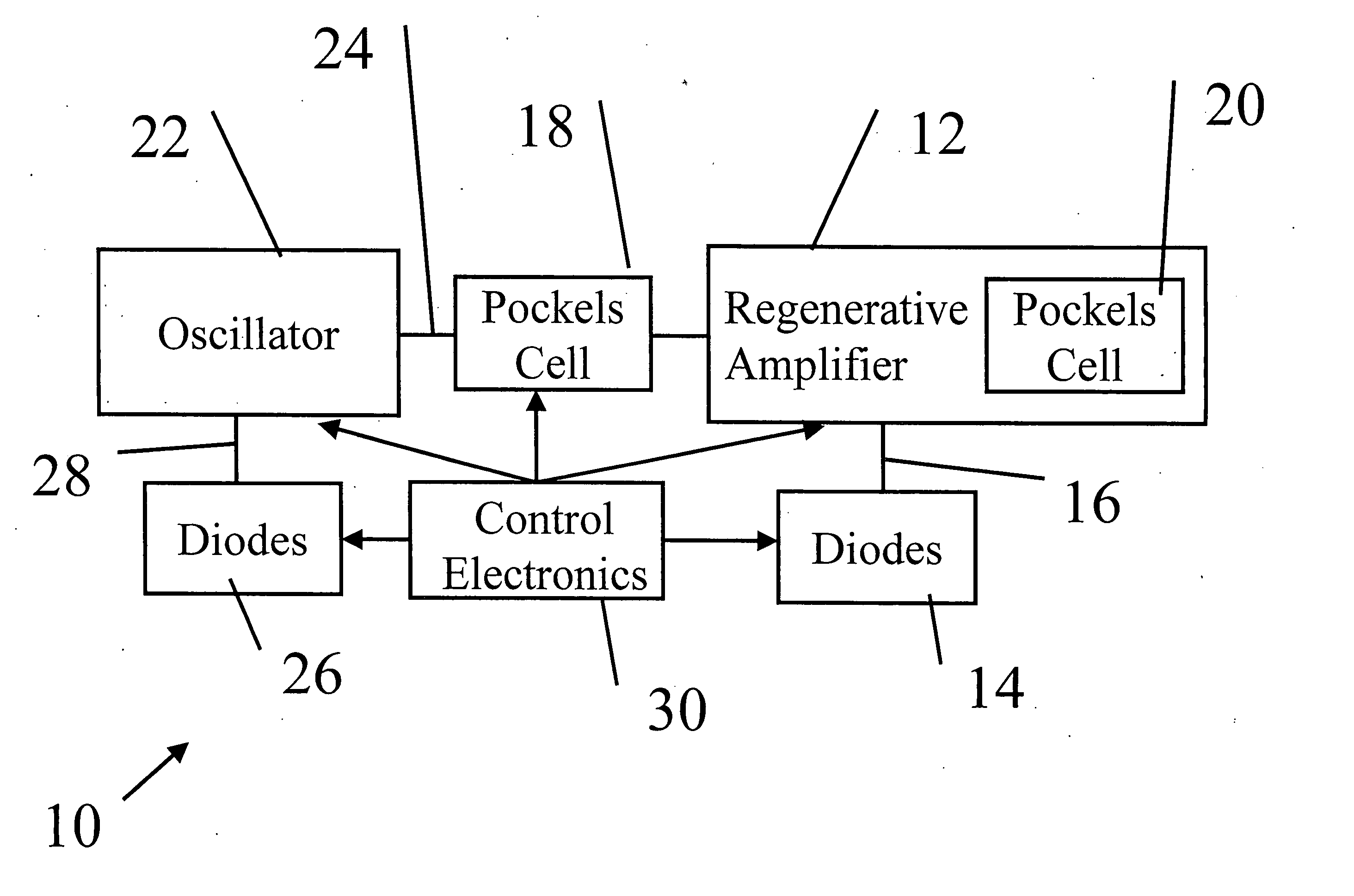
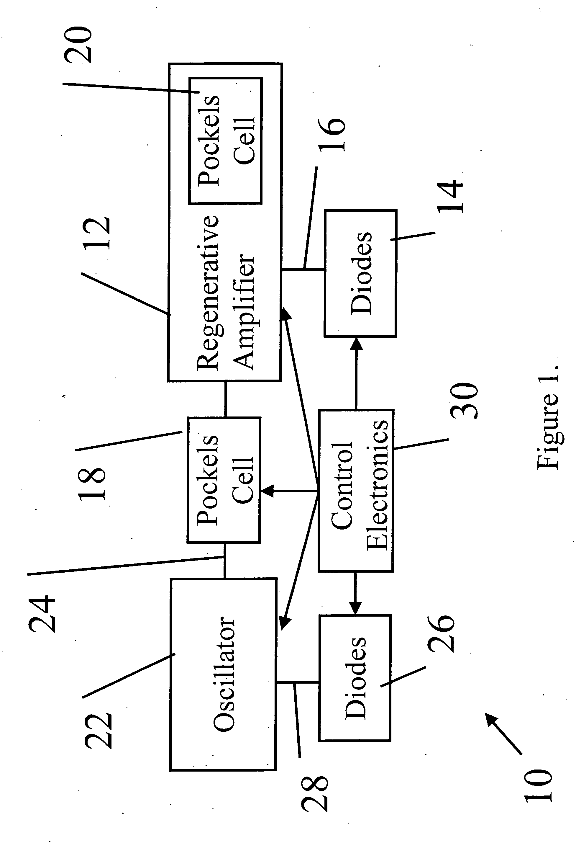
[0023] As illustrated in FIG. 1, in one embodiment of the present invention, a regenerative amplifier system, generally denoted as 10, includes a regenerative amplifier cavity 12 and a pump source 14 that produces a pump beam 16. The power of pump beam 16 can vary. In various embodiments, pump beam 16 can a power in the range of, of 1-100 W, 1-30 W, 1-10 W, and the like. The amount of pump power is selected depending on the output power desired. Pump beam 16 can have a variety of wavelengths, including but not limited to a wavelength in the range of 800 to 1000 nm.
[0024] A first electro-optic switch 18 is positioned external to regenerative amplifier cavity 12 (hereafter “cavity 12”). A second electro-optic switch 20 is positioned in cavity 12. An oscillator 22 is coupled to first electro-optic switch 18 and produces multiple seed pulses 24.
[0025] A pump source 26 produces a pump beam 28 for oscillator 22. In various embodiments, pump source 26 can be selected from a diode, a diod...
PUM
 Abstract
Description
Claims
Application Information
PatSnap Eureka turns technology decisions into work you can execute. Powered by our Innovation Knowledge Graph, it runs expert workflows across engineering, life sciences, materials and intellectual property. Get your review-ready output in minutes.


