Container conveying system

a conveying system and container technology, applied in the direction of furniture, charge manipulation, lighting and heating apparatus, etc., can solve the problems of insufficient conveyancing capacity and treatment capacity of the above conveyancing means, long time taken in case of a longer transfer distance, and inability to achieve long-distance conveyancing capacity, so as to improve the treatment capacity of the container, improve the treatment capacity, and maximize the effect of spa

Inactive Publication Date: 2005-07-21
HIRATA & CO LTD
View PDF15 Cites 23 Cited by
  • Summary
  • Abstract
  • Description
  • Claims
  • Application Information

AI Technical Summary

Benefits of technology

[0037] In a preferred mode, plural branch conveyance paths are formed at appropriate intervals in the conveyance direction of the conveyance apparatus and are able to receive the containers having been conveyed by the conveyance apparatus and allow the containers to stand by; and the transfer apparatus can hold the stand-by containers on the branch conveyance paths and deliver the containers to any of the treatment apparatuses. Thus, the containers which have been received by the branch conveyance paths can stand by in a standstill state on the branch conveyance paths until the transfer apparatus carries the containers to a predetermined treatment apparatus. That is, it is not necessary for the containers to stand by on the conveyance apparatus for the transfer onto the transfer apparatus, and thus the containers do not obstruct other containers forwarding by being conveyed by the conveyance apparatus. As a result, the container treatment capacity can be further improved as a whole.
[0038] In another preferred mode, plural treatment apparatuses are arranged on both sides of a passage, the conveyance apparatus is provided with two conveyance apparatus units traveling respectively along two conveyance paths which are a going path and a returning path; and the transfer apparatuses are provided on the right and left sides respectively of the conveyance apparatus. According to this arrangement, in the intra-clean room production line wherein the plural treatment apparatuses are arranged on both sides of the passage, both conveyance means (the conveyance apparatus and the transfer apparatus) can be arranged concentratively and symmetrically right and left in the upper ceiling space while ensuring the worker passage centrally; and thus the conveyance and transfer of containers to the plural treatment apparatuses on both sides of the passage can be taken charge of by both conveyance means (the conveyance apparatus and the transfer apparatus) disposed on the right and left sides, whereby it is possible to utilize the space effectively and further improve the container treatment capacity. Besides, it becomes possible to place a larger number of containers on the conveyance apparatus and the stock function, stand-by function and sorting function of the container conveying system can be further expanded.
[0039] In a further preferred mode, the two conveyance paths are arranged transversely in parallel. As a result, the structure of the conveyance apparatus including a transfer mechanism or the like for connecting the two conveyance apparatus units which travel along the two going and returning conveyance paths can be simplified.
[0040] In a still further preferred mode, the two conveyance paths are arranged vertically in parallel. According to this arrangement, since the two conveyance apparatus units which travel along the two going and returning conveyance paths respectively are disposed as one above the other and are thus assembled three-dimensionally, the space between the treatment apparatuses (treatment apparatus groups) arranged on both sides of the paths becomes narrower. Although the worker passage becomes a little narrower as saving the space to a minimum requirement, it is possible to further decrease the equipment cost and the maintenance cost of the clean room.

Problems solved by technology

However, none of the above conveyance means can yet be said as satisfactory in terms of conveyance capacity and treatment capacity.
The first problem resides in the conveyance capacity in long-distance conveyance.
However, a long time may be taken in case of a longer transfer distance.
The second problem is that in a conveyance system constituted by a single conveyance apparatus, even if it is an overhead traveling type container conveying system, there is a limitation in terms of treatment capacity.
However, there is a limitation in terms of treatment capacity because each of the containers conveying systems disclosed therein is constituted by a single conveyance apparatus.
The third problem is that it is difficult to improve the treatment capacity without increasing the footprint of the conveyance means.
The fourth problem is that the container stock function is insufficient.
Further, the fifth problem is that the container sorting function is not provided.

Method used


Image

  • Container conveying system
  • Container conveying system
  • Container conveying system

Examples


first embodiment

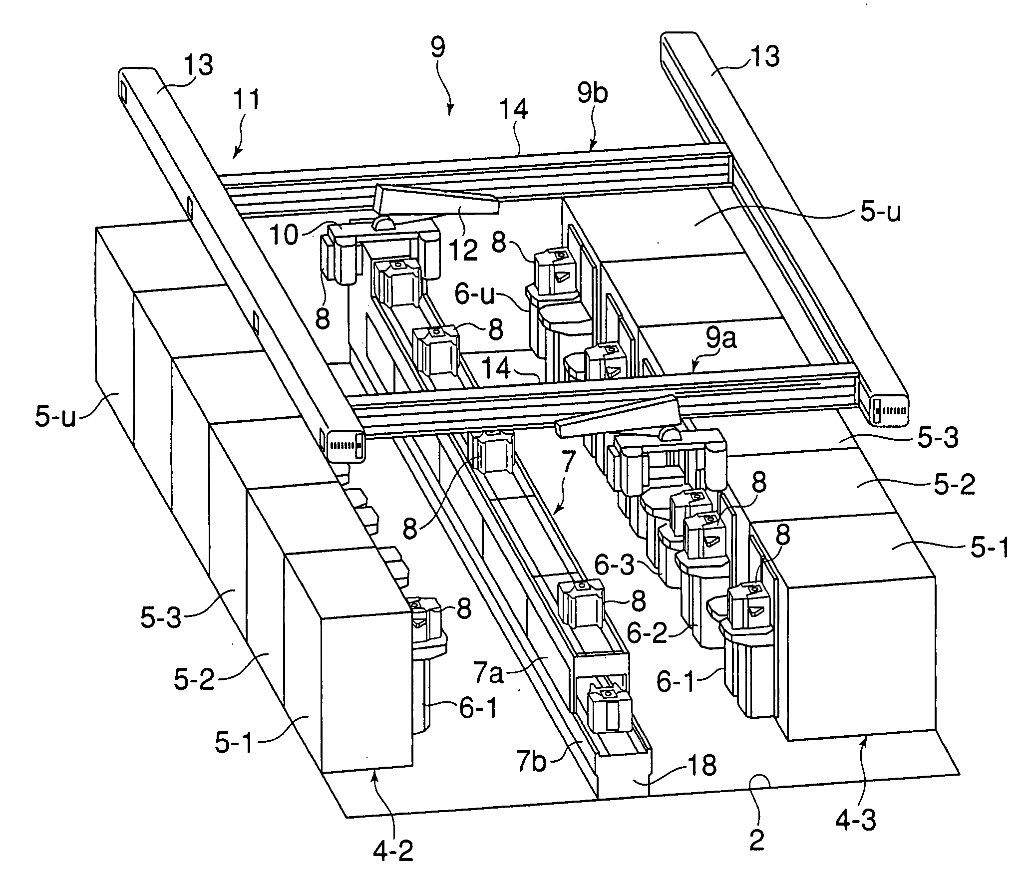
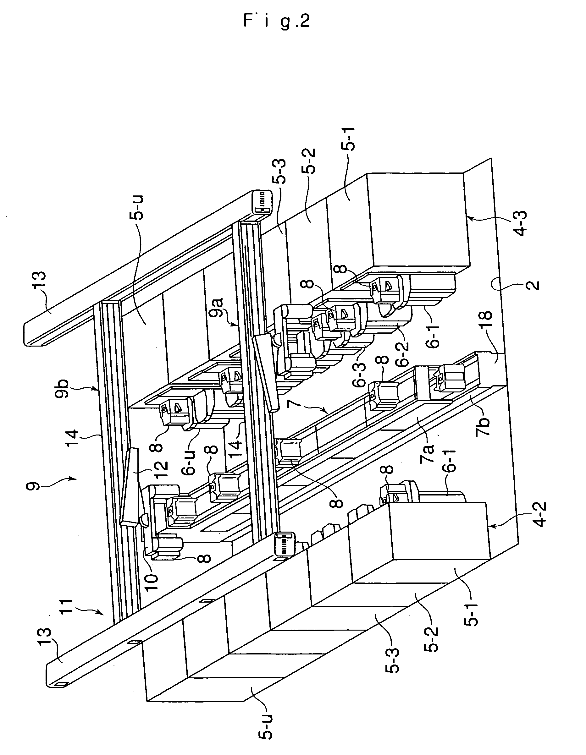
[0052] A container conveying system according to the present invention is used for the conveyance of containers such as FOUP or SMIF pods containing various substrates such as semiconductor substrates including wafers and reticles, or glass substrates, between plural treatment apparatuses installed in an intra-clean room production line particularly in a manufacturing factory for the manufacture of semiconductor devices or liquid crystal devices.

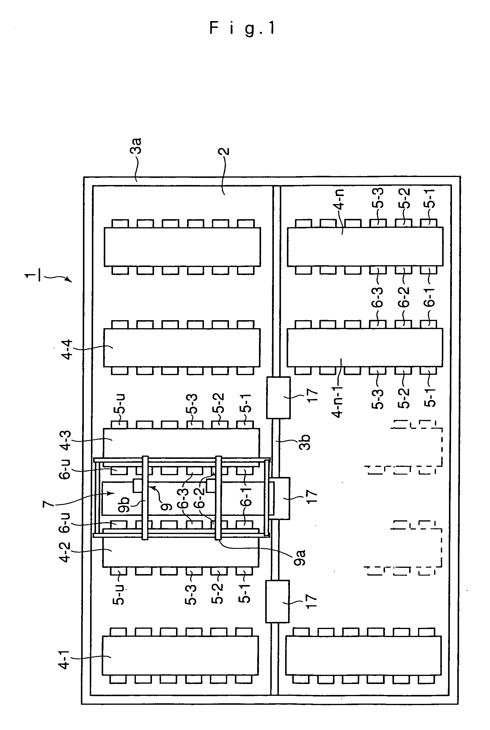
[0053] A layout of a treatment area in the intra-clean room production line in the manufacturing factory as mentioned above is shown in FIG. 1.

[0054] In an intra-clean room production line 1, as shown in FIG. 1, plural treatment apparatus groups 4-1, 4-2, 4-3, . . . 4-n are arranged side by side in the direction along a central inter-process conveyance path 3b within both areas adjacent to each other on both sides of the linear inter-process conveyance path 3b, the both areas being partitioned by a rectangular inter-conveyance path 3a exten...

second embodiment

[0102] Next, a container conveying system according to another embodiment (second embodiment) of the present invention will be described below.

[0103] In the container conveying system of this second embodiment, as shown in FIG. 5, a conveyance apparatus 7 has two conveyance paths disposed on the right and left sides on top of a base 18 self-standing up on a floor surface 2, and a left conveyance apparatus unit 7a and a right conveyance apparatus unit 7b traveling along the conveyance paths respectively are provided.

[0104] Only in this point the second embodiment is different from the first embodiment, with other constructional points being the same. Therefore, a detailed description will here be omitted.

[0105] In the container conveying system of this second embodiment constructed as above, the whole conveyance apparatus unit 7b which in the first embodiment underlies the conveyance apparatus unit 7a appears to the exterior. Consequently, loading and unloading of containers 8 onto...

third embodiment

[0109] A container conveying system according to a further embodiment (third embodiment) of the present invention will be described below.

[0110] In this third embodiment, in one area of the intra-clean room production line, as shown in FIGS. 6 and 7, treatment apparatus groups 4-2 and 4-3 are respectively arranged on both sides of a central passage 23. Further, in the ceiling space above the passage 23, a conveyance apparatus 7 is provided along the passage 23 and transfer apparatuses 20 are provided on both sides of the conveyance apparatus 7. The two transfer apparatuses 20 can move freely in a vertical plane (a two-dimensional space) running along the conveyance apparatus 7 through the upper ceiling space within the clean room.

[0111] Each of the treatment apparatus groups 4-2 and 4-3 comprises plural treatment apparatuses 5-1, 5-2, 5-3, . . . The treatment apparatuses 5-1, 5-2, 5-3, . . . are arranged regularly in one row along the passage 23 and are respectively provided with i...


PUM


Abstract

A container conveying system for conveying containers 8 containing substrates such as wafers within a clean room comprises a conveyance apparatus 7 disposed substantially in parallel with plural treatment apparatuses 5-1, 5-2, 5-3, . . . to convey the containers 8 and a transfer apparatus 9 capable of moving freely in an upper ceiling space within the clean room, characterized in that the plural treatment apparatuses 5-1, 5-2, 5-3, . . . are arranged on at least one side of a passage and respectively provided with interface devices 6-1, 6-2, 6-3, . . . on the side facing the passage; the interface devices 6-1, 6-2, 6-3, . . . are capable of temporarily receiving the containers 8 and moving the substrates from the interiors of the containers to the interiors of the treatment apparatuses 5-1, 5-2, 5-3, . . . and vice versa in a hermetically sealed atmosphere; and the transfer apparatus 9 delivers and receives the containers 8 between the conveyance apparatus 7 and the treatment apparatuses 5-1, 5-2, 5-3, . . . or between the treatment apparatuses 5-1, 5-2, 5-3, . . . According to this container conveying system, the container conveying capacity, the treatment capacity, the footprint, the container stock function and the sorting function are further improved.

Description

TECHNICAL FIELD [0001] The present invention relates to a container conveying system and more particularly to an improvement of a container conveying system capable of freely conveying containers such as FOUP or SMIF pods which contain substrates such as semiconductor wafers, reticles, or glass substrates between plural treatment apparatuses or between plural treatment apparatuses and a conveying apparatus in a manufacturing factory for the manufacture of semiconductor devices or liquid crystal devices. BACKGROUND ART [0002] In a manufacturing process for the manufacture of semiconductor integrated circuits or liquid crystal display panels, the product yield is reduced due to adhesion of dusts or particles to such substrates as wafers, reticles, or glass substrates. To avoid this inconvenience, an intra-clean room production line operates and various improvements are made for container conveying equipment and systems which can convey containers freely among various treatment apparat...

Claims


Application Information

Patent Timeline
Patent Type & Authority Applications(United States)
IPC IPC(8): B65G47/10H01L21/677
CPCH01L21/67727H01L21/6773H01L21/67769H01L21/67736H01L21/67733
Inventor OTAGURO, TETSUNORI
Owner HIRATA & CO LTD
Why Eureka
Try Eureka