Methods and apparatus for coupling ceramic matrix composite turbine components

a composite turbine and ceramic matrix technology, applied in the direction of machines/engines, liquid fuel engines, lighting and heating apparatus, etc., can solve the problems of premature failure of the fastener assembly, limited performance and stability of the rotor assembly, and increased tip leakag

Active Publication Date: 2005-07-21
GENERAL ELECTRIC CO
View PDF11 Cites 52 Cited by
  • Summary
  • Abstract
  • Description
  • Claims
  • Application Information

AI Technical Summary

Problems solved by technology

During operation, tip leakage across the rotor blade tips may limit the performance and stability of the rotor assembly.
However, during operation, because the shrouds may be subjected to higher operating temperatures than the stator block, the shrouds may thermally expand at a different rate than the stator block or the fastener assemblies used to couple the shrouds to the stator block.
More specifically, the differential thermal expansion may undesirably cause increased tip leakage as the operating temperature within the engine is increased.
In addition, over time, the heat transfer from the shrouds and the differential thermal expansion may also cause premature failure of the fastener assemblies.
However, excessive cooling flow may adversely affect engine performance.
However, although such materials should enable the shrouds to be exposed to higher operating temperatures, the operation of the engine may still be limited by the increased thermal differential expansion rates between the shrouds and the stator block through the fastener assemblies.

Method used


Image

  • Methods and apparatus for coupling ceramic matrix composite turbine components
  • Methods and apparatus for coupling ceramic matrix composite turbine components
  • Methods and apparatus for coupling ceramic matrix composite turbine components

Examples


Embodiment Construction

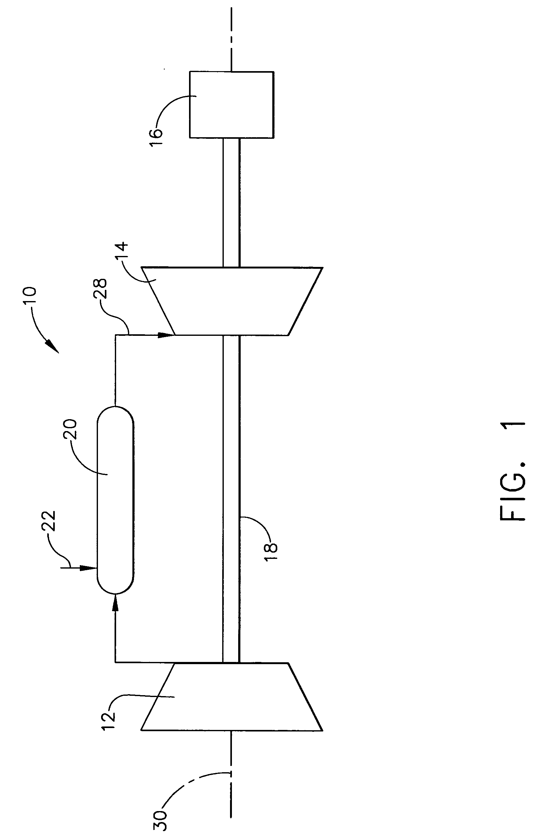
[0013]FIG. 1 is a schematic illustration of an exemplary gas turbine engine 10 coupled to an electric generator 16. In the exemplary embodiment, gas turbine system 10 includes a compressor 12, a turbine 14, and generator 16 arranged in a single monolithic rotor or shaft 18. In an alternative embodiment, shaft 18 is segmented into a plurality of shaft segments, wherein each shaft segment is coupled to an adjacent shaft segment to form shaft 18. Compressor 12 supplies compressed air to a combustor 20 wherein the air is mixed with fuel supplied via a stream 22. In one embodiment, engine 10 is a 6FA+e gas turbine engine commercially available from General Electric Company, Greenville, S.C.

[0014] In operation, air flows through compressor 12 and compressed air is supplied to combustor 20. Combustion gases 28 from combustor 20 propels turbines 14. Turbine 14 rotates shaft 18, compressor 12, and electric generator 16 about a longitudinal axis 30.

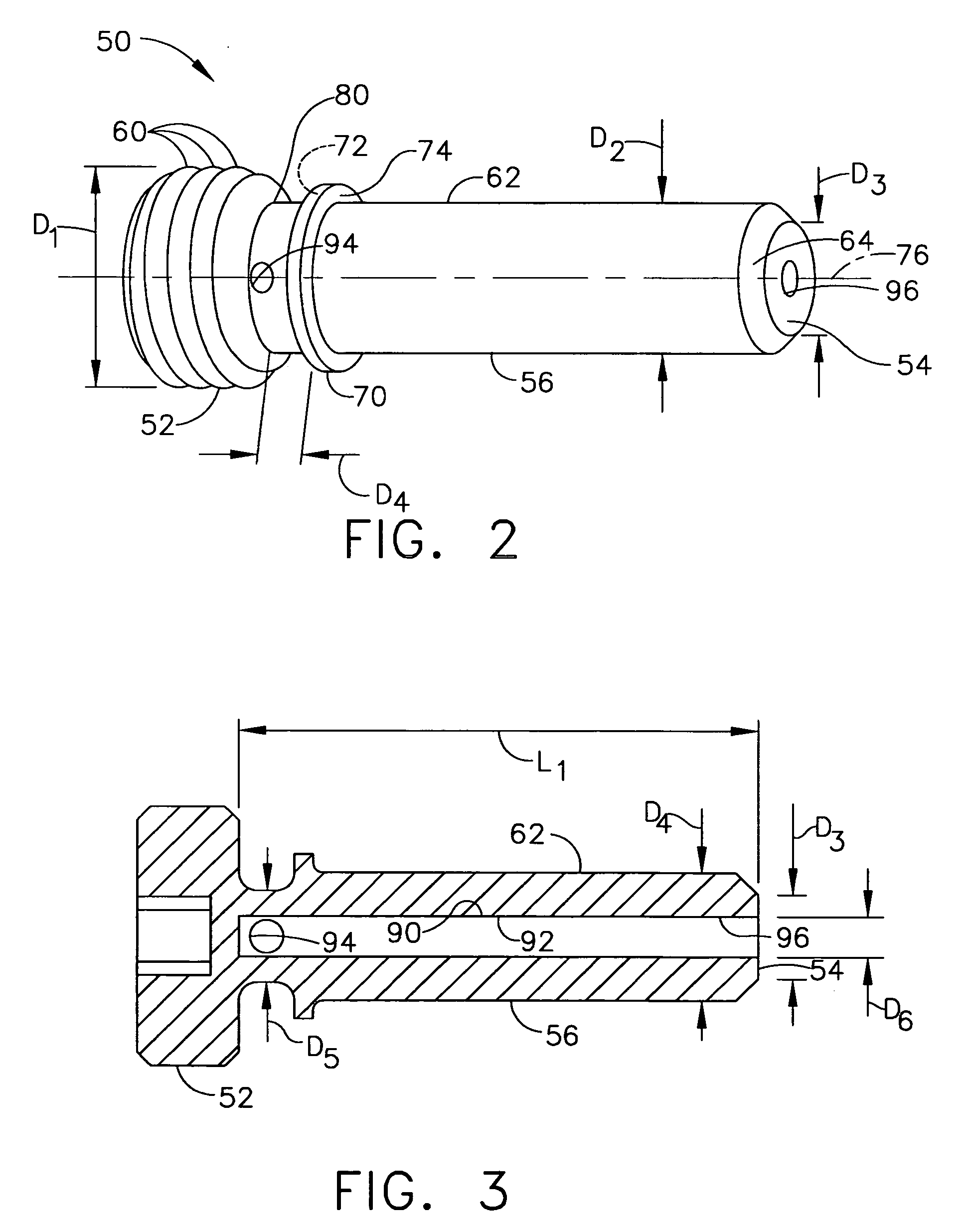
[0015]FIG. 2 is an enlarged side view of a...


PUM


Abstract

A method facilitates assembling a stator assembly for a turbine engine. The method comprises positioning a shroud fabricated from a ceramic matrix composite material adjacent a metallic stator block, and coupling the shroud to the stator block using a coupling arrangement such that a predetermined radial clearance is defined between the shroud and a rotor assembly coupled radially inward thereof.

Description

BACKGROUND OF THE INVENTION [0001] This application relates generally to turbine engines and, more particularly, to methods and apparatus for assembling turbine engine components that are fabricated from ceramic matrix composite materials. [0002] Turbine engines include at least one stator assembly and at least one rotor assembly. At least some known rotor assemblies include at least one row of circumferentially-spaced rotor blades. The blades extend radially outward from a platform to a tip. A plurality of static shrouds coupled to a stator block abut together to form flowpath casing that extends circumferentially around the rotor blade assembly, such that a radial tip clearance is defined between each respective rotor blade tip and the casing or shroud. The tip clearance is tailored to be a minimum, yet is sized large enough to facilitate rub-free engine operation through the range of available engine operating conditions. [0003] During operation, tip leakage across the rotor blad...

Claims


Application Information

Patent Timeline
Patent Type & Authority Applications(United States)
IPC IPC(8): F01D9/04F01D11/08F01D25/08
CPCF01D9/04F01D11/08F05D2260/231F05D2240/11F05D2260/30F01D25/08
Inventor BRUCE, KEVIN LEONBUCCI, DAVID VINCENTCAIRO, RONALD RALPHMITCHELL, DAVID
Owner GENERAL ELECTRIC CO
Why Eureka
Try Eureka