
Method and apparatus for digital detection of electronic markers using frequency adaptation

a technology of electronic markers and frequency adaptation, applied in mechanical devices, using reradiation, instruments, etc., can solve the problems of inability to identify and distinguish among various types of utility conduits and conductors, and inability to use line locator devices to locate non-conductive lines. , to achieve the effect of high-quality identification of marker types

Active Publication Date: 2005-07-21
BUSAN TRANSPORTATION CORPORATION
View PDF10 Cites 24 Cited by
  • Summary
  • Abstract
  • Description
  • Claims
  • Application Information

AI Technical Summary

Benefits of technology

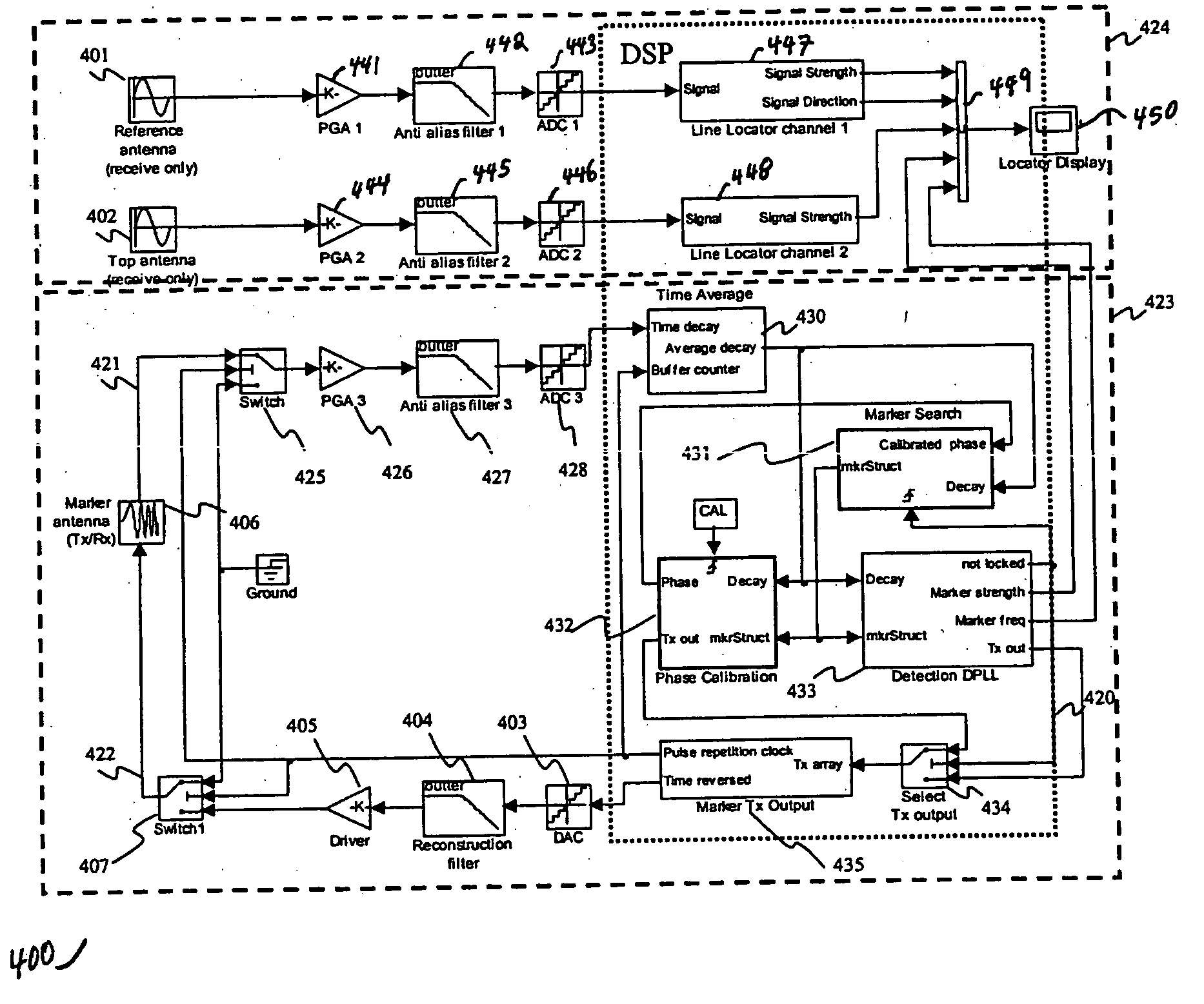
[0010] In accordance with the present invention, a marker locator receiver digital architecture is described that provides for digital marker and line location. In this fashion, highly accurate identification of marker type and depth determination can be accomplished.
[0013] Additionally, in some embodiments a dual-mode locator that simultaneously offers both line and marker location methods is presented. Using such embodiments, an operator using conventional line tracing methods (with a separate transmitter to directly or inductively couple the signal at an access point) can also be warned of the presence of one or more electronic markers in the same vicinity. Furthermore, in some embodiments multiple marker types can be searched for simultaneously, and the user can be alerted to the presence of each marker type as encountered. When ambiguities in marker type and signal strength exist due to a “neighbor detection” or “near-far” problem, it is advantageous for a marker locator to be able to reliably discriminate targeted marker types from others using a quantitative method. During the search phase of marker location (for example, a background marker search activity while in line-locate mode), a frequency adaptation mechanism can be included to create the highest possible signal-to-noise ratio (SNR) in the reflected marker signal response. Finally in the lock phase, when an individual marker is known and locked onto by the marker locator, accurate and repeatable signal strength estimates can be attained prior to invoking a depth calculation.

Problems solved by technology

Utility conduits are often buried underground or concealed in walls and therefore are not readily accessible or identifiable.
A disadvantage with relying solely on the line locator device is that it may fail to identify and distinguish among various types of utility conduits and conductors.
Additionally, line locator devices cannot be used to locate non-conductive lines, such as, for example, gas lines, fiber optic lines and plastic water lines when those non-conductive lines are not marked with trace wires.
Again, significant difficulty in marker type identification and depth determination may result, especially if multiple markers of differing types and depths are present.

Method used


Image

  • Method and apparatus for digital detection of electronic markers using frequency adaptation
  • Method and apparatus for digital detection of electronic markers using frequency adaptation
  • Method and apparatus for digital detection of electronic markers using frequency adaptation

Examples


Embodiment Construction

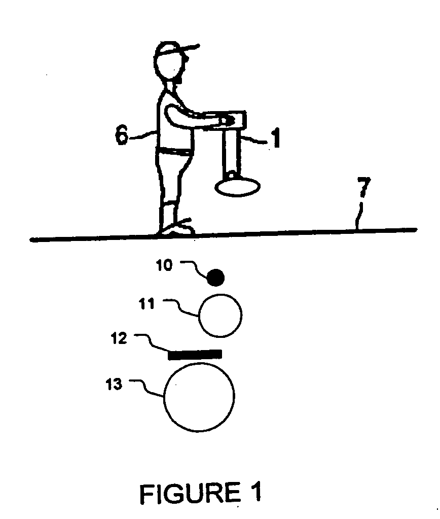
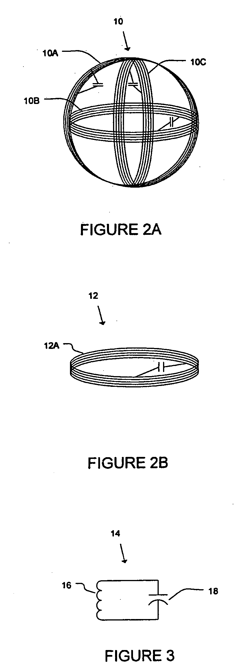
[0034] Generally, electronic markers consist of two types, namely, active markers and passive markers. Active markers, radiate a signal detectable at the surface; however, they require a power source. Passive markers, on the other hand, require no power source and become active when induced by an external electromagnetic field, which can be generated with a portable power source.

[0035] A marker locator is a device for detecting and determining the location of concealed or buried markers. Passive markers typically include a multi-turn wire loop (coil) tuned with a capacitor to a pre-determined resonant frequency. A flexible implementation of an electromagnetic marker locator is described in U.S. patent application Ser. No. 10 / 227,149, “Procedure and Device for Determining the Location of Buried Electronic Markers,” by Hubert Schlapp and Richard Allin, which is herein incorporated by reference in its entirety. A fully digital implementation of an electromagnetic line locator is descr...


PUM


Abstract

An electronic marker locator with a digital architecture for providing accurate and consistent estimation of the signal strength is presented. The marker locator includes a Digital Phase-Locked Loop (DPLL) structure. The electronic marker locator transmits known and adjustable frequency bursts corresponding to the markers to be located while synchronously capturing the signals returned from the markers. Because of the convergence properties of the DPLL, very consistent measurements of the reflected marker signal field strength are possible, resulting in both an improvement of maximum detection depth and depth accuracy. Further, the analog front-end hardware can be reduced, offering wider resistance to component tolerances, lower calibration and test times, and flexible frequency selectivity.

Description

BACKGROUND [0001] 1. Field of the Invention [0002] The present invention is directed toward detection of concealed electronic markers that are commonly buried alongside pipes or cables and, in particular, to a digital implementation of a combined pipe and cable locator device to simultaneously search for buried markers with high accuracy and repeatability. [0003] 2. Discussion of Related Art [0004] Utility conduits are often buried underground or concealed in walls and therefore are not readily accessible or identifiable. It is often necessary to locate these concealed utility conduits in order to repair and replace them. It is also important to know the location of utility conduits in order to avoid them while excavating an area. Examples of hidden utility conduits include pipelines for gas, sewage, or water and cables for telephone, television, or power. [0005] There are various ways to locate concealed objects, for example, using line locators or marker locators. Line locators ar...

Claims


Application Information

Patent Timeline
Patent Type & Authority Applications(United States)
IPC IPC(8): G01V15/00
CPCG01V15/00F16L1/11
Inventor OVERBY, JOHAN D.WAITE, JAMES W.
Owner BUSAN TRANSPORTATION CORPORATION
Learn More