System & method for asynchronous logic synthesis from high-level synchronous descriptions

a logic synthesis and high-level technology, applied in the field of digital logic, can solve the problems of absolute guarantee deterioration, incomplete logic design no longer operating safely, and complexity negatively affecting the cad tool or human designer of the physical circui

Active Publication Date: 2005-07-21
TEXAS INSTR INC
View PDF1 Cites 37 Cited by
  • Summary
  • Abstract
  • Description
  • Claims
  • Application Information

AI Technical Summary

Benefits of technology

[0021] A system and method for asynchronous logic synthesis from high-level synchronous descriptions. More particularly, a method is disclosed for generating an equivalent asynchronous handshake circuit from a synchronous description of its intended behavior.

Problems solved by technology

Asynchronous logic is no different in that timing assumptions put constraints on design.
Implementation complexity negatively impacts a CAD tool or human designer of the physical circuit.
In some cases this absolute guarantee deteriorates performance because of the more robust event signaling protocol which must be used.
During physical implementation of the design, each wire attached to a gate contains a hard and fast time delay constraint, beyond which the entire logic design no longer operates safely.
For a design of modem proportions, containing hundreds of thousands or millions of such wires, this assumption is usually unmanageable.
Clearly, reducing the number of timing constraints by orders of magnitude ameliorates a great burden on implementation complexity.
However, nondeterminism makes testing of asynchronous logic designs extremely difficult, as the same input applied repetitively to the same physical circuit yields results in different order each time.
HDLs for asynchronous design entry have struggled for standardization and acceptance due to the complexities of describing the asynchronous event control.
Between the set of locally clocked registers under event control, the datapath has a known worst-case bundled delay.

Method used


Image

  • System & method for asynchronous logic synthesis from high-level synchronous descriptions
  • System & method for asynchronous logic synthesis from high-level synchronous descriptions
  • System & method for asynchronous logic synthesis from high-level synchronous descriptions

Examples


Embodiment Construction

[0034] In the following description, for purposes of explanation, numerous details are set forth in order to provide a thorough understanding of the present invention. However, it will be apparent to one skilled in the art that these specific details are not required in order to practice the present invention. In some instances, well-known electrical structures and circuits are shown in symbolic or block diagram form in order not to obscure the present invention.

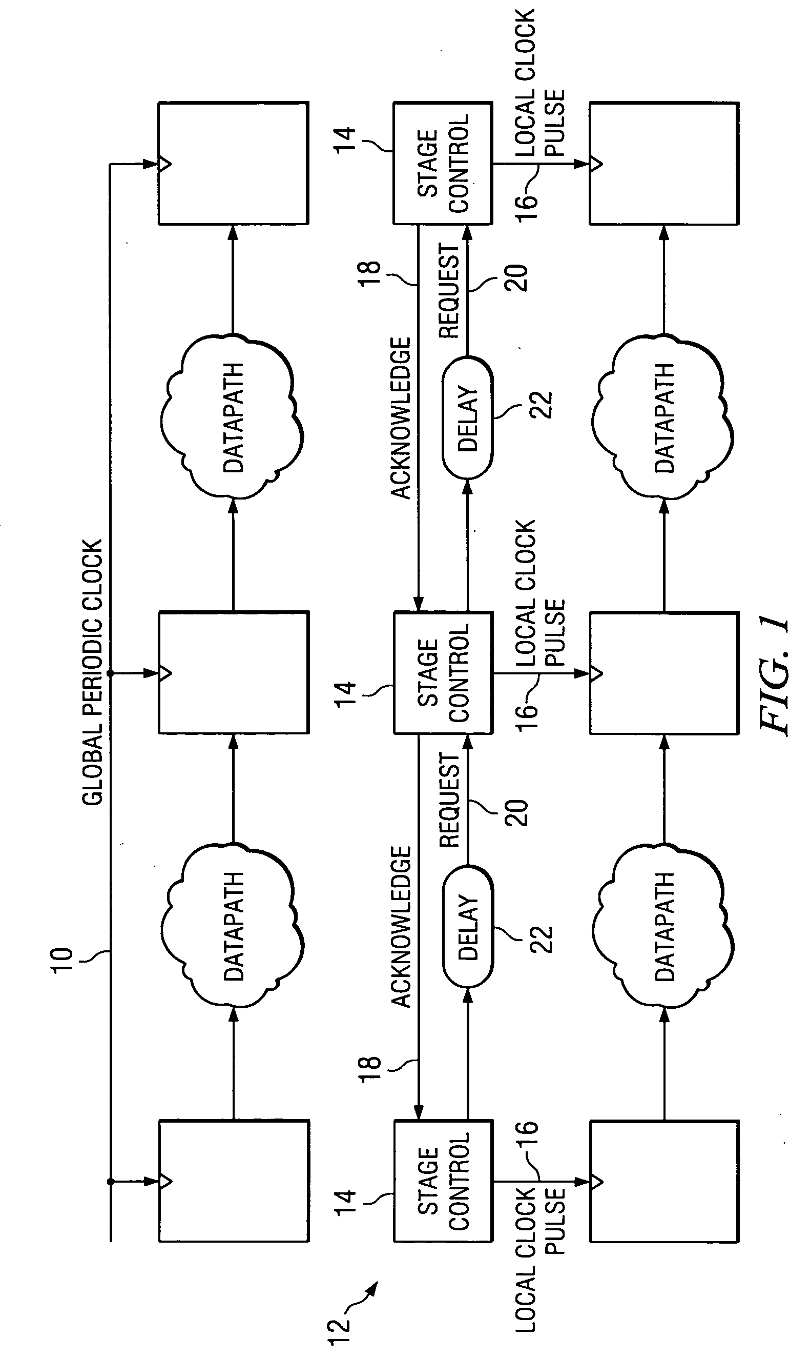
[0035]FIG. 1 is a diagram illustrating an example of the fundamental transformation from synchronous logic to Micropipelines using asynchronous handshakes, for which the present invention is employed. The global clock 10 in an original synchronous design is replaced by a two-phase asynchronous handshake network 12. Each bank of state elements in the original design is replaced with stage control logic 14 including a local clock 16, backwards acknowledge signal 18 and request signal 20 delayed by a matched delay element 22. ...


PUM


Abstract

A method for generating an equivalent asynchronous handshake circuit from a synchronous description of its intended behavior.

Description

[0001] This application is claims priority to application Ser. No. 60 / 537,873 filed Jan. 20, 2004.FIELD OF THE INVENTION [0002] The invention relates to digital logic. In particular, the invention relates to the methodology used to design asynchronous handshake digital logic circuits. BACKGROUND OF THE INVENTION [0003] In the design of digital logic, it is a fundamental task to be able to sequence behavior in time where required. For example, an operation X must not be activated without its proper data operands A and B ready and available, and any other operations Y and Z which use the result of X must both be finished and ready to accept a new result from X. The former requirement is known as a dependency, and the latter known as an antidependency. [0004] Synchronous logic solves the problem of sequencing behavior in digital designs by activating all operations on the occurrence of a single, global event. This global event is the rising or falling edge of a periodic clock signal. C...

Claims


Application Information

Patent Timeline
Patent Type & Authority Applications(United States)
IPC IPC(8): G06F3/00G06F17/50
CPCG06F17/5059G06F30/35
Inventor SANDBOTE, SAM BRANDON
Owner TEXAS INSTR INC
Why Eureka
Try Eureka