Method for manufacturing an armature

a manufacturing method and technology for armatures, applied in the manufacture of magnetic bodies, resistive material coatings, magnetic cores, etc., can solve the problems of short service life of armatures and insufficient strength of connecting joints to withstand the swing of armatures, and achieve the effect of increasing the strength of joints

Active Publication Date: 2005-07-28
TOSHIBA TEC KK
View PDF34 Cites 21 Cited by
  • Summary
  • Abstract
  • Description
  • Claims
  • Application Information

AI Technical Summary

Benefits of technology

[0008] In view of the above problems with the related art, the present invention has an object of providing an armature manufacturing method for increasing the strength of the joint connecting an arm and magnetic circuit forming members.

Problems solved by technology

The magnetic circuit forming members welded in this state to the arm are prone to easily separate from the arm, and the armature has only a short service life.
The smaller size of the arm and magnetic circuit forming members makes them difficult to spot weld so that the connecting joint does not have sufficient strength to withstand the swing of the armature.

Method used


Image

  • Method for manufacturing an armature
  • Method for manufacturing an armature
  • Method for manufacturing an armature

Examples


Embodiment Construction

[0019] An embodiment of the armature manufacturing method of the present invention is described next while referring to the accompanying drawings.

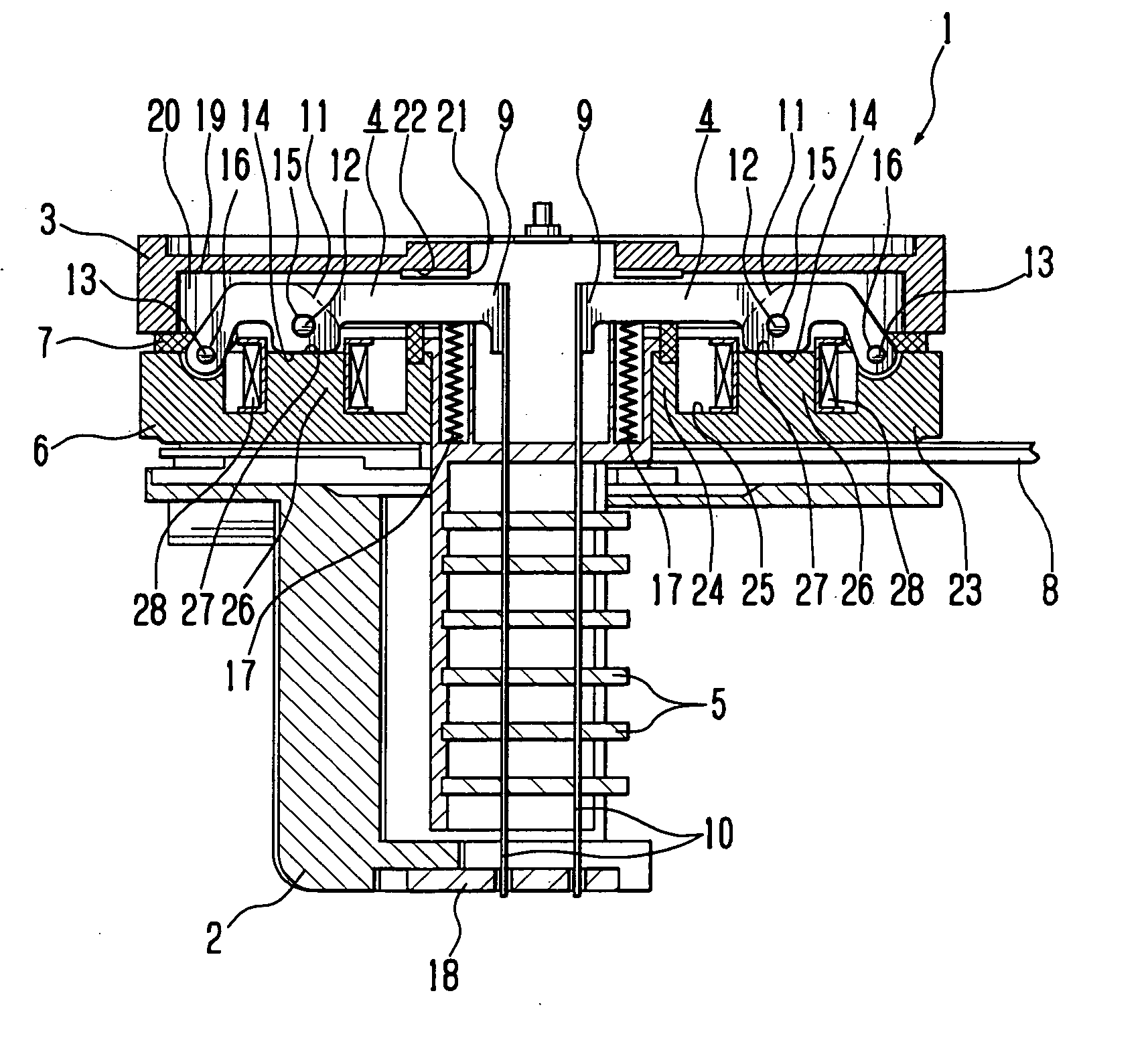
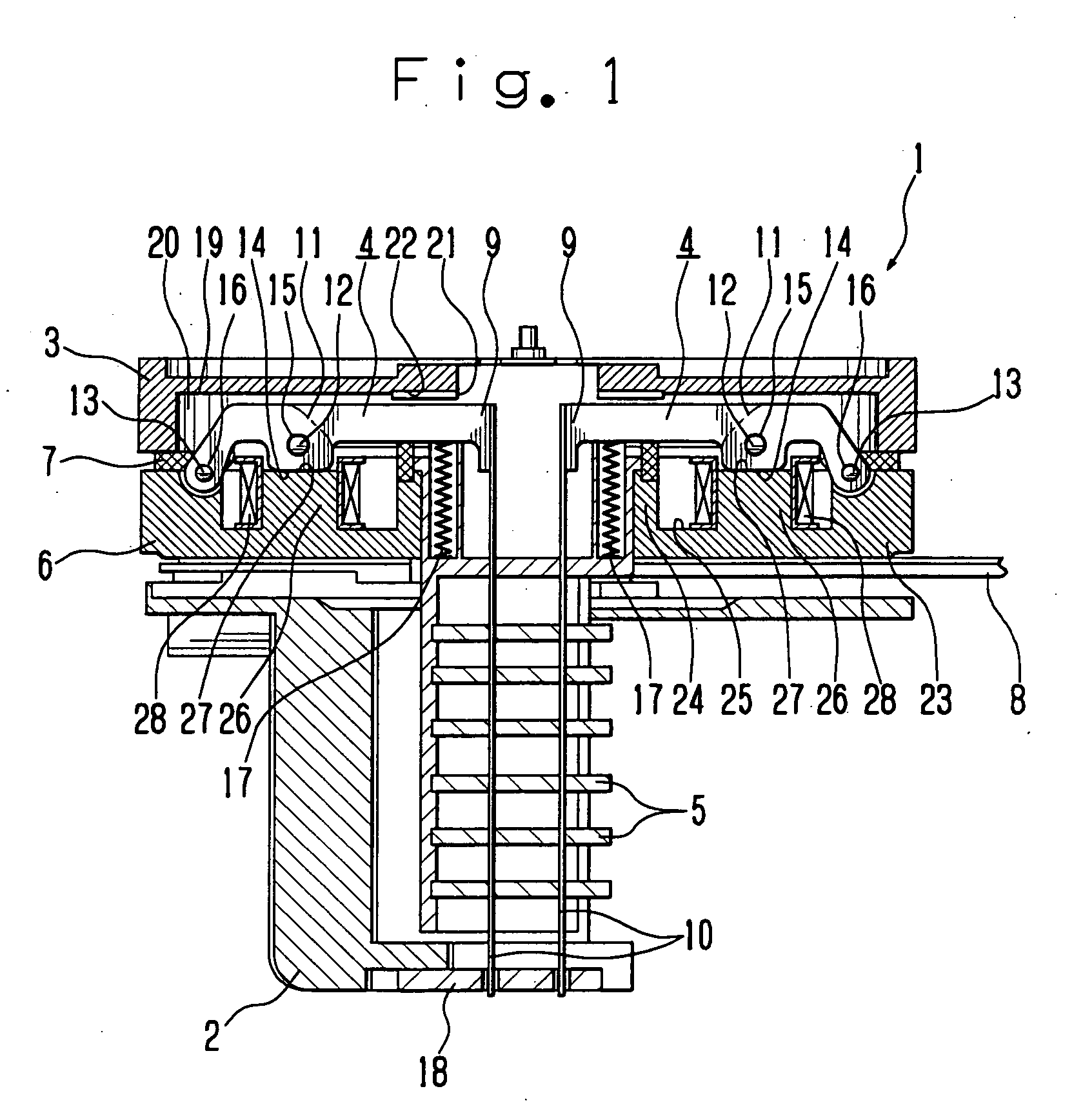
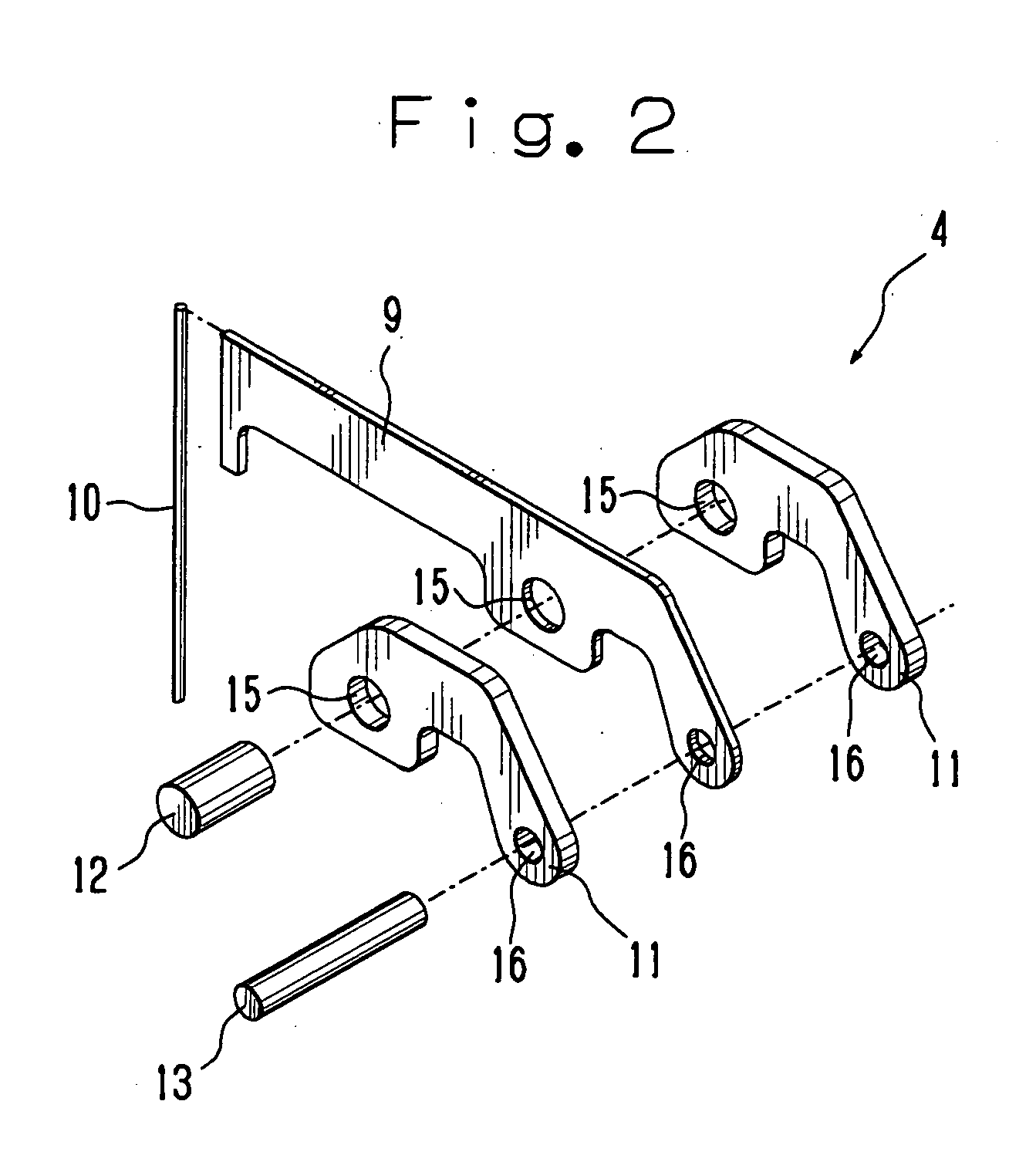
[0020] Print Head 1 The overall structure of a print head 1 for a wire dot matrix printer is described while referring to FIG. 1 and FIG. 2. FIG. 1 is a longitudinal sectional view of the print head 1 in the wire dot matrix printer. FIG. 2 is an exploded perspective view of an armature 4 in the print head-1.

[0021] The print head 1 has a case formed by fastening a front case 2 and a rear case 3 together by set screws (not shown in drawing). The armatures 4, wire guides 5, a yoke 6, armature spacers 7 and a wiring board 8 are provided inside this print head 1 case.

[0022] The armature 4 contains a flat arm 9, a printing wire (hereinafter simply called “wire”) 10 attached length-wise on the arm 9 (direction in which arm 9 extends) by brazing, magnetic circuit forming members 11 respectively welded to the opposite side surfaces in the thickn...


PUM

PropertyMeasurementUnit
thicknessaaaaaaaaaa
diameteraaaaaaaaaa
thickaaaaaaaaaa

Abstract

An armature manufacturing method of forming an armature including an arm holding a printing wire, and magnetic circuit forming members attached to the arm places the magnetic circuit forming members on the arm with a resistive layer of a resistive material having high electric resistance sandwiched between the arm and each of the magnetic circuit forming members, and welds together the arm and the magnetic circuit forming members with the resistive films sandwiched between the arm and the magnetic circuit forming members by spot welding. The arm and the magnetic circuit forming members of the armature can be joined together by welds having a high weld strength.

Description

BACKGROUND OF THE INVENTION [0001] 1. Field of the Invention [0002] The present invention relates to a method for manufacturing an armature used in print heads in wire dot matrix printers. [0003] 2. Discussion of the Background [0004] In a print head in a wire dot matrix printer, an armature connected to printing wires is turned between a printing position and a waiting position. When the armature is turned to the printing position the tips of the wires strike a printing medium such as paper to perform printing. Print heads of this type wire dot matrix printer contain a coil that generates a magnetic flux around an armature to form a magnetic circuit capable of attracting the armature from the waiting position to the printing position. [0005] The armature includes an arm and magnetic circuit forming members attached to both side surfaces in the thickness direction of the arm. A printing wire is attached to the arm by brazing. The magnetic circuit forming members are attached to the ...

Claims


Application Information

Patent Timeline
Patent Type & Authority Applications(United States)
IPC IPC(8): B41J2/275B41J2/23H01F7/06H01F7/08H01F41/02
CPCB41J2/23H01F7/081H01F41/0206Y10T29/49099Y10T29/4902Y10T29/49128Y10T29/49078
Inventor KAWAGUCHI, TAKAHIRO
Owner TOSHIBA TEC KK
Why Eureka
Try Eureka