Method of forming fracture start portion of ductile metal part and fracture start portion forming device

a technology of ductile metal parts and starting parts, which is applied in the direction of manufacturing tools, machines/engines, transportation and packaging, etc., can solve the problems of inability to obtain a clean connection-rod fracture surface in some cases, and the fusion is more than necessary at a portion

Active Publication Date: 2005-07-28
YASUNAGA CO LTD THE
View PDF13 Cites 18 Cited by
  • Summary
  • Abstract
  • Description
  • Claims
  • Application Information

AI Technical Summary

Benefits of technology

[0010] An object of the present invention is to provide a method of forming a fracture start portion of a ductile metal part and a fracture start portion forming device as well as a method of fracturing a ductile metal part and a fracturing device which can form a fracture start portion of a ductile metal part according to design dimension without being affected by heat from an adjacent recess portion due to laser irradiation and can obtain a clean fracture surface through the fracture start portion of this ductile metal part.

Problems solved by technology

In the above methods of forming a groove for fracturing a connecting rod in a patent document 1 and a patent document 2, since laser is irradiated onto an inner circumferential surface of a connecting-rod large end with a fine pulse so as to form a so-called groove for fracture, influence of heat generated at a (specific) irradiation position of the laser is excessively transmitted to an adjoining position of the groove, and there is a fear that this extra heat might cause fusion more than necessary at a portion adjacent to the groove.
Therefore, when such a groove not in the desired shape is formed as a connecting-rod fracture start portion, a clean connecting-rod fracture surface can not be obtained in some cases.

Method used


Image

  • Method of forming fracture start portion of ductile metal part and fracture start portion forming device
  • Method of forming fracture start portion of ductile metal part and fracture start portion forming device
  • Method of forming fracture start portion of ductile metal part and fracture start portion forming device

Examples


Embodiment Construction

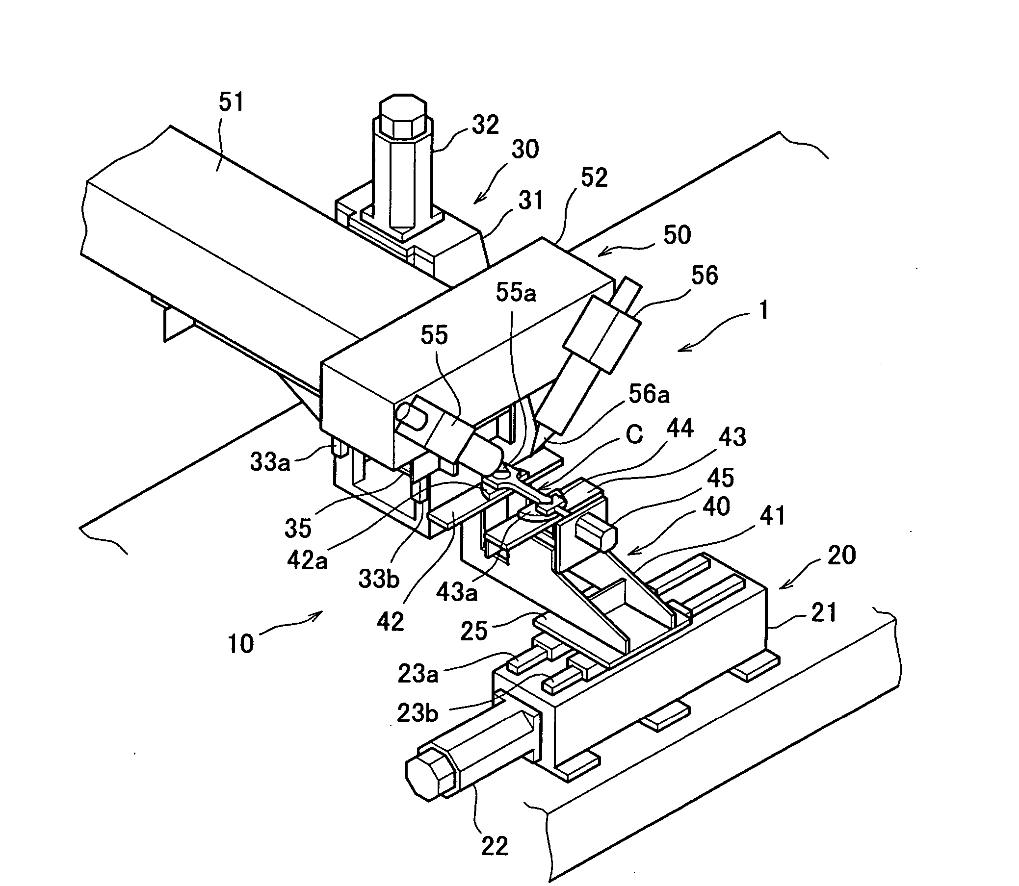
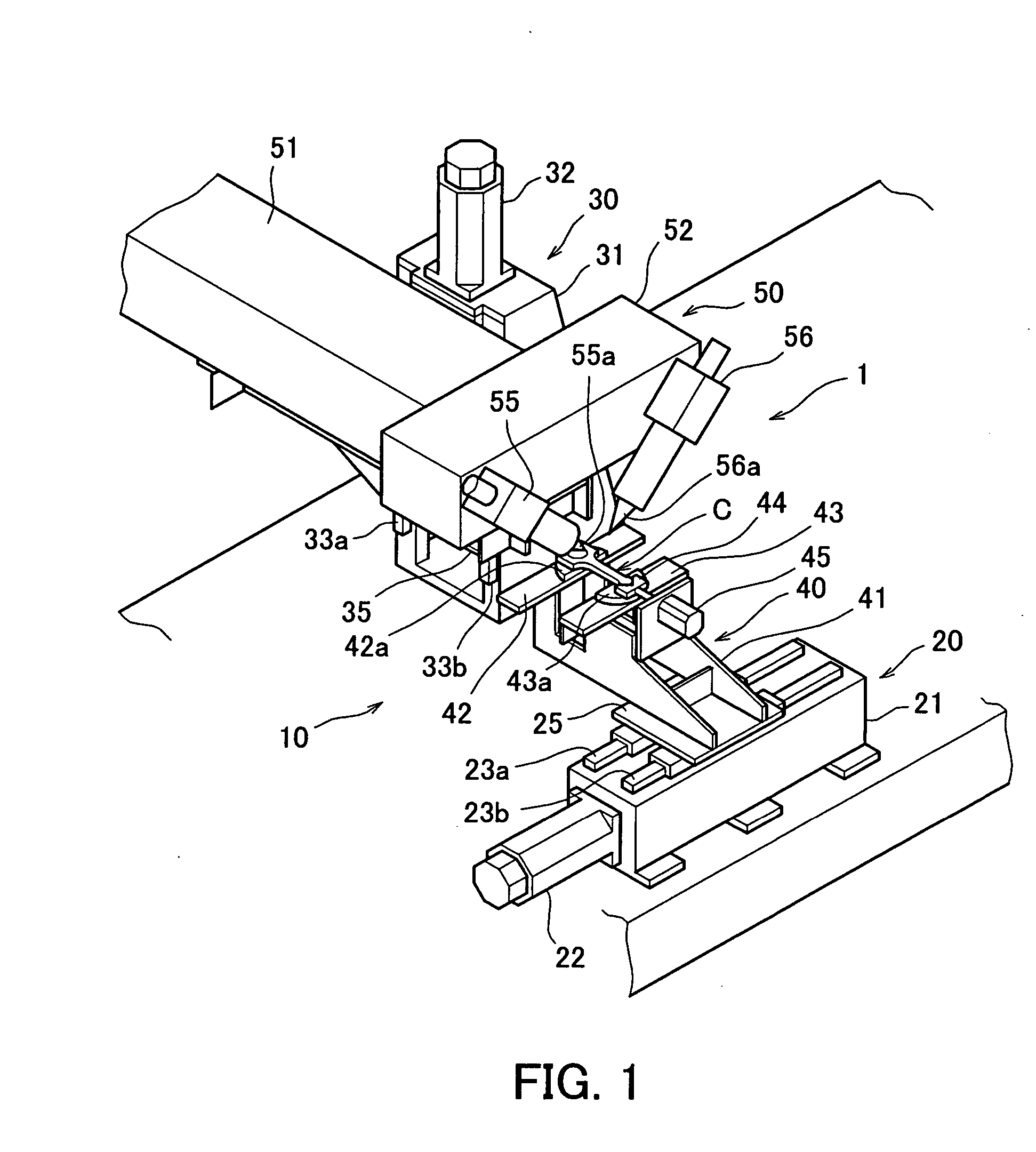
[0060] A fracturing device of a ductile metal part provided with a fracture start portion forming device of the ductile metal part according to a preferred embodiment of the present invention will be described below together with its fracture start portion forming method and a fracturing method. In the present invention, as a preferred embodiment of the fracturing device of a ductile metal part provided with the fracture start portion forming device of the ductile metal part, a so-called connecting-rod fracture start portion forming device and a connecting rod fracturing device will be described.

[0061] First, the connecting-rod fracture start portion forming device will be described based on the drawings.

[0062] Constitution of the connecting-rod fracture start portion forming device 1 is as shown in FIG. 1. To be concrete, the connecting-rod fracture start portion forming device is provided with a bed (base) 10 made of an elongated rectangular thick plate, an X-axis table device 2...


PUM

PropertyMeasurementUnit
frequencyaaaaaaaaaa
depthaaaaaaaaaa
distanceaaaaaaaaaa

Abstract

This is a method of forming a fracture start portion of a ductile metal part on an inner circumferential face of a through hole by irradiating laser to an opposing position of the inner circumferential face of the thorough hole of the ductile metal part having a predetermined through hole and by forming a large number of recess portions separated with a predetermined distance at a predetermined interval from one opening to the other opening of the through hole, in which a recess part is formed, instead of by focusing the laser exactly onto the inner circumferential face of the through hole, by irradiating it onto the inner circumferential face of the through hole while defocusing from the inner circumferential face of the through hole by a predetermined amount as well as by supplying an assist gas to a position of the laser irradiation, and the laser is moved linearly at a predetermined speed from one side opening to the other side opening on the inner circumferential face of the through hole while irradiating the laser onto the inner circumferential face of the through hole at a predetermined pulse.

Description

BACKGROUND [0001] 1. Field of the Invention [0002] The present invention relates to a forming method and a forming device of a fracture start portion required when stretching and fracturing a ductile metal part such as a connecting rod, for example, as well as a fracturing method and a fracturing device of a ductile metal part. [0003] 2. Description of the Related Art [0004] A halved part obtained by stretching and fracturing a ductile metal part is combined again to be used as a pair of products in some cases. An example of such a part is a connecting rod known as a part for vehicles. And a method of fracturing a connecting rod by applying a tensile stress on a large end of the connecting rod among the large end and a small end provided respectively at both ends of the connecting rod has been known. In such a fracturing method, a technique to form a groove of a large width and a small depth at a fracture portion through machining has been used for a long time (See, for example, U.S...

Claims


Application Information

Patent Timeline
Patent Type & Authority Applications(United States)
IPC IPC(8): B23D31/00B23K26/382B23P19/00B23P19/02
CPCB23D31/003B23K26/385F16C9/045Y10T29/49288Y10T29/49821Y10T29/4979Y10T29/49796Y10T29/49824B23K26/389B23K26/142B23K26/02B23K2101/30B23K26/386B23K26/14B23K26/083B23K26/0869B23K2101/006B23K26/0665
Inventor HASE, HIROICHI
Owner YASUNAGA CO LTD THE
Why Eureka
Try Eureka