Surface treatment facility of metal plate, method for producing metal plate and system for producing metal plate

Inactive Publication Date: 2005-07-28
JFE STEEL CORP
View PDF4 Cites 10 Cited by
  • Summary
  • Abstract
  • Description
  • Claims
  • Application Information

AI Technical Summary

Benefits of technology

[0017] It is an object of the present invention to provide an apparatus for surface treatment which is able to efficiently create a surface roughness on a steel sheet even when the steel s

Problems solved by technology

That is, blasting solid particles against the surface of steel sheet converts the kinetic energy of the solid particles into

Method used


Image

  • Surface treatment facility of metal plate, method for producing metal plate and system for producing metal plate
  • Surface treatment facility of metal plate, method for producing metal plate and system for producing metal plate
  • Surface treatment facility of metal plate, method for producing metal plate and system for producing metal plate

Examples


example 1

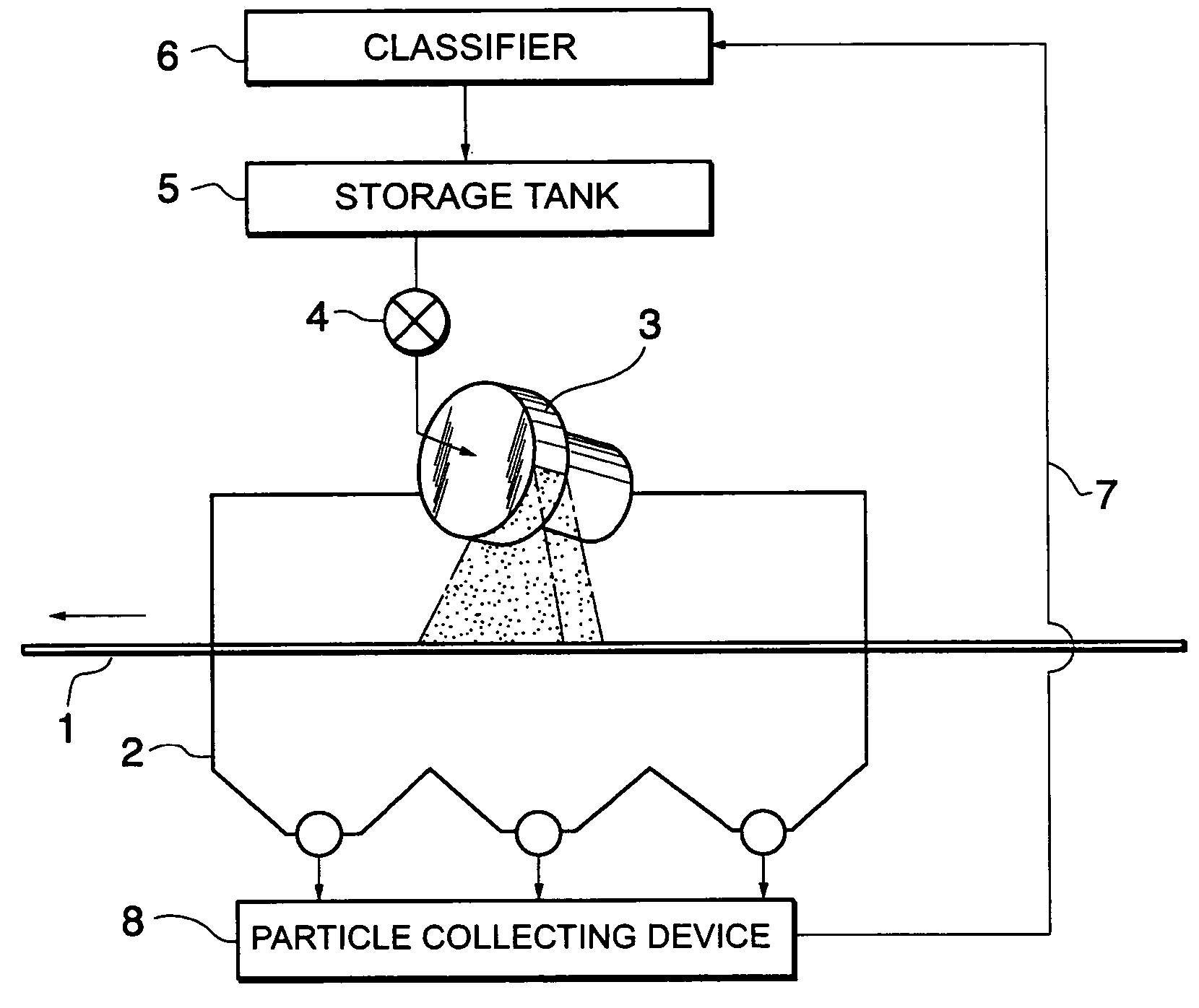
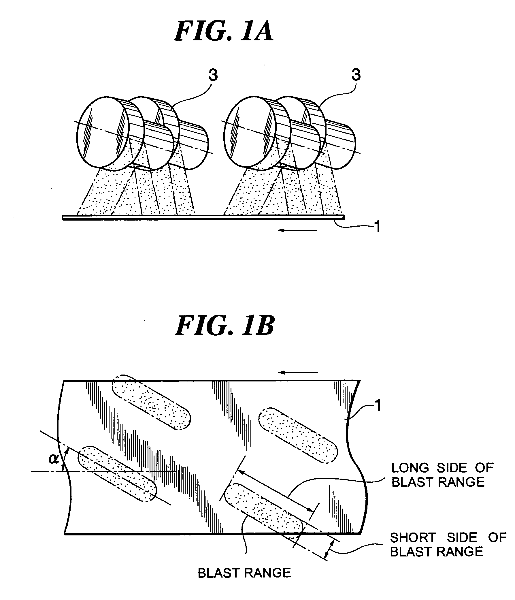
[0075] Example 1 according to the present invention is the result of creating a roughness on the surface of steel sheet using four units of centrifugal blasting machines given in FIG. 1. Also there is given the description of a comparative example which is the result of creating a roughness on the surface of steel sheet using two units of centrifugal blasting machines given in FIG. 8. For the case of FIG. 1, the line of intersection between the plane vertical to the rotation axis of the centrifugal rotor and the plane of the steel sheet was set to have an angle á of 30° to the direction of travel of the steel sheet. For the case of FIG. 8, on the other hand, the line of intersection between the plane vertical to the rotation axis of the centrifugal rotor and the plane of the steel sheet was set to become vertical to the direction of travel of the steel sheet.

[0076] Example 1 used a hot-dip galvanized steel sheet as the steel sheet to create a surface roughness. The hot-dip galvaniz...

example 2

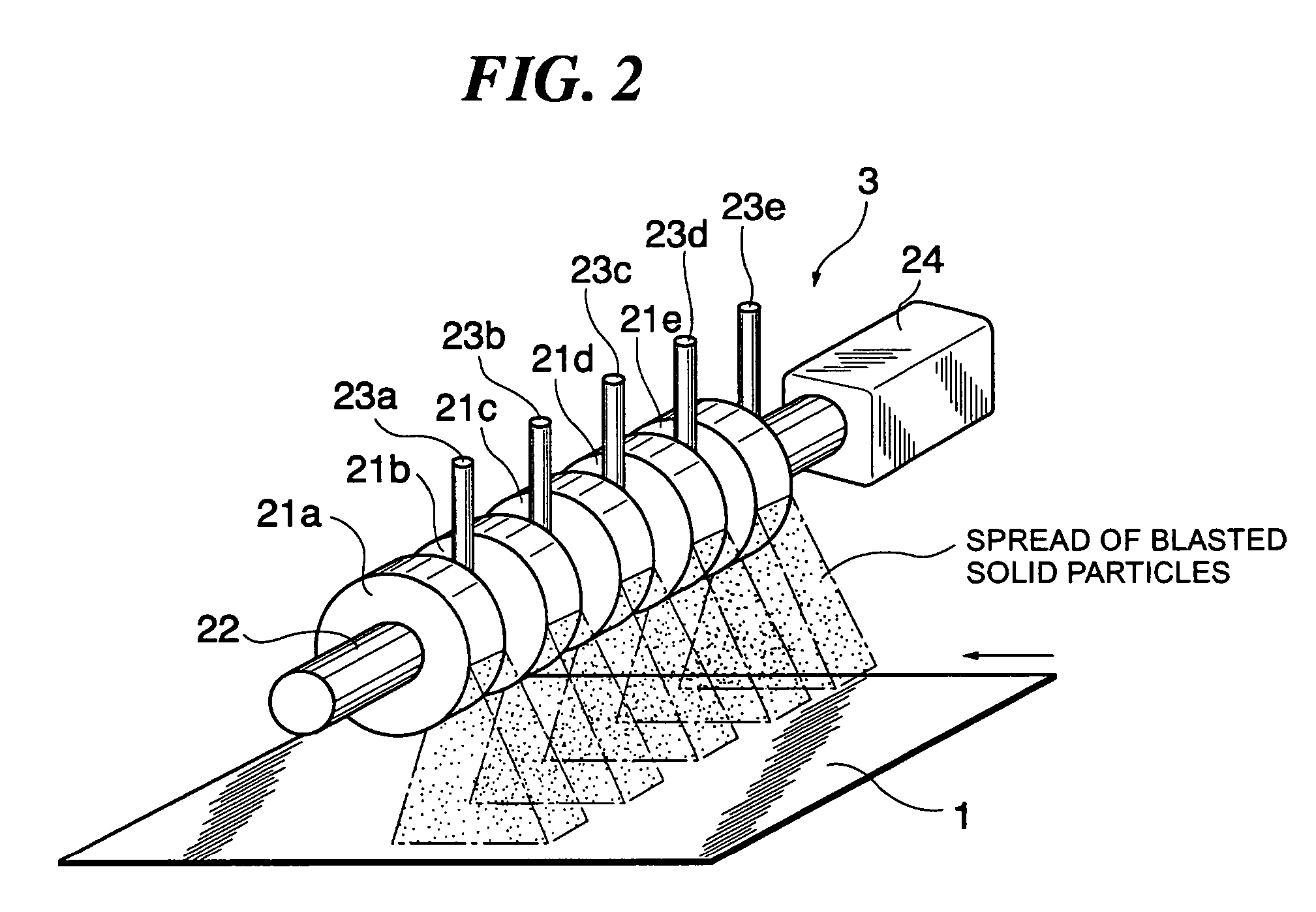
[0086] Example 2 according to the present invention is the result of creating a roughness on the surface of steel sheet using the centrifugal blasting machine given in FIG. 2. In this case, the line of intersection between the plane vertical to the rotation axis of the centrifugal rotor and the plane of the steel sheet was set to become parallel to the direction of travel of the steel sheet. As a comparative example, the description is given also to the result of creating a roughness on the surface of steel sheet using two units of centrifugal blasting machines applied in Example 1, shown in FIG. 8.

[0087] Example 2 according to the present invention is the result of creating a roughness on the surface of steel sheet using the centrifugal blasting machine given in FIG. 2. In this case, the line of intersection between the plane vertical to the rotation axis of the centrifugal rotor and the plane of the steel sheet was set to become parallel to the direction of travel of the steel sh...

example 3

[0099] Example 3 according to the present invention is the result of creating a roughness on the surface of steel sheet using: the centrifugal blasting machines arranged as given in FIG. 1, applied in Example 1, (hereinafter referred to as the “arrangement A”); and the centrifugal blasting machines arranged as given in FIG. 2, applied in Example 2, (hereinafter referred to as the “arrangement B”).

[0100] According to the arrangement A, the line of intersection between the plane vertical to the rotation axis of the centrifugal rotor of the centrifugal blasting machine and the plane of the metallic sheet is set to have an angle á (á=30°) to the direction of travel of the metallic sheet. The arrangement gives the blast ranges shown in FIG. 17. For the arrangement B, the line of intersection between the plane vertical to the rotation axis of the centrifugal rotor of the centrifugal blasting machine and the plane of the metallic sheet is set to become parallel (á=0°) to the direction of ...


PUM

PropertyMeasurementUnit
Angleaaaaaaaaaa
Angleaaaaaaaaaa
Particle diameteraaaaaaaaaa

Abstract

A surface treatment apparatus for metallic sheet has at least one centrifugal blasting machine to blast solid particles having 30 to 300 μm of mean particle diameter against the continuously traveling metallic sheet. The blasting machine is structured by a centrifugal rotor having a rotation axis. The line of intersection between the plane vertical to the rotation axis and the plane of the metallic sheet is positioned in parallel to or at 45° or smaller angle to the travel direction of the metallic sheet.

Description

FIELD OF THE INVENTION [0001] The present invention relates to an apparatus for surface treatment on producing a metallic sheet such as galvanized steel sheet having excellent press formability and image sharpness after coating by creating a surface roughness configured by dense microscopic irregularities on the surface thereof by blasting fine solid particles against the surface of the metallic sheet, and relates to a method for producing metallic sheet as an application of the apparatus, and specifically relates to an apparatus for surface treatment being able to efficiently create a surface roughness even under a high line speed, further to an apparatus for surface treatment being able to provide a compact design therefor, a method for producing metallic sheet using the apparatus, a hot-dip coating line of metallic sheet using the apparatus, and a continuous annealing line of metallic sheet using the apparatus. DESCRIPTION OF THE PRIOR ARTS [0002] Thin steel sheets such as those ...

Claims


Application Information

Patent Timeline
IPC IPC(8): B24C3/14B24C9/00
CPCB24C3/14C21D7/06B24C9/006Y02P70/10B24C5/06
Inventor KIMURA, YUKIOUENO, MASAYASUSODANI, YASUHIRO
Owner JFE STEEL CORP
Why Eureka
Try Eureka