
Drive of variable valve lift mechanism

Inactive Publication Date: 2005-07-28
HONDA MOTOR CO LTD
View PDF3 Cites 2 Cited by
  • Summary
  • Abstract
  • Description
  • Claims
  • Application Information

AI Technical Summary

Benefits of technology

[0007] The present invention has been achieved in view of the above situation, and has an object to provide a drive of a variable valve lift mechanism for preventing an engine body from being complex and improving the maintainability.
[0009] With the arrangement of the first feature, an independently constituted drive is attached to the outside of the engine body. Therefore, the engine body does not become complex. Also, the drive can be singly attached to and detached from the engine body, to thereby contribute to improvement of maintainability.
[0011] When attaching the independently-constituted drive to the engine body, it is generally performed to form an oil path concavely in the mating faces between a cylinder head and a drive in order to supply lubricating oil, or to form an exclusive oil path in the cylinder head by casting-out or machining. However, these techniques have difficulty in the process for forming the oil path, and it is necessary to increase the capacity of an oil pump corresponding to increase of oil quantity. Moreover, increase of the pump friction due to increase of the back pressure of a lubricating oil supply path results in output loss of the engine. However, according to the second feature, the lubricating oil splashed into the head cover or the oil leaking from the bearing portion of the cam shat are stored in the oil reservoir, and then supplied to the drive side by gravitation. Therefore, additional energy is unnecessary for supply of oil, and thus power loss due to the additional energy does not occur. Moreover, it is only necessary to form an oil reservoir at a part of the cam holder, and an oil path can be formed by comparatively simple drilling. Thus, it is possible to minimize increase of the manufacturing cost.
[0013] With this third feature, the shaft line of the output shaft of the rotational force generating actuator is disposed on the plane orthogonal to the shaft line of the control shaft, and attached to the outer face of the casing. Therefore, it is possible to suppress the amount of protrusion of the rotational force generating actuator and the casing out of the engine body in the direction along the shaft line of the control shaft; make compact the whole structure including the rotational force generating actuator and the casing in the shaft line direction of the control shaft; and prevent the size of an engine from increasing. Moreover, the rotational force output from the output shaft of the rotational force generating actuator is transferred to the screw shaft through the reduction gear mechanism. Therefore, it is possible to decrease the size of the rotational force generating actuator to make the actuator more compact.
[0015] With this fourth feature, when attaching the casing to the outer face of the sidewall of the engine body, it is possible to easily improve accuracy in the connection between the control shaft in which at least a part of the circumference of the holder is rotatably supported and the power conversion means in the casing, by fitting the positioning section of the holder to the fitting hole of the casing of the engine body; and it is possible to attach the casing to the outer face of the sidewall of the engine body while accuracy in the connection between the control shaft and the power conversion means is improved, by providing a slight allowance for the setting position of the casing to the outer face of the sidewall of the engine body.
[0017] According to a sixth feature of the present invention, in addition to the arrangement of the third feature, a sensor is coaxially arranged on the control shaft so as to detect pivoting amount of the control shaft, and is attached to a wall portion of the casing opposite to the one end of the control shaft. With this arrangement, it is possible to accurately detect the rotation amount of the control shaft by setting a sensor so as to coaxially face an end of the control shaft. Even if setting the sensor in this way, it is possible to make compact the whole structure including the rotational force generating actuator, casing, and sensor in the shaft line direction of the control shaft, thereby suppressing the increase of the size of the engine.

Problems solved by technology

However, using a configuration in which the main part of a driving mechanism is built in an engine body leads to disadvantages that not only the structure of the engine becomes complex but also the engine body need to be inevitably disassembled to a certain extent for maintenance of the driving mechanism.

Method used


Image

  • Drive of variable valve lift mechanism
  • Drive of variable valve lift mechanism
  • Drive of variable valve lift mechanism

Examples


second embodiment

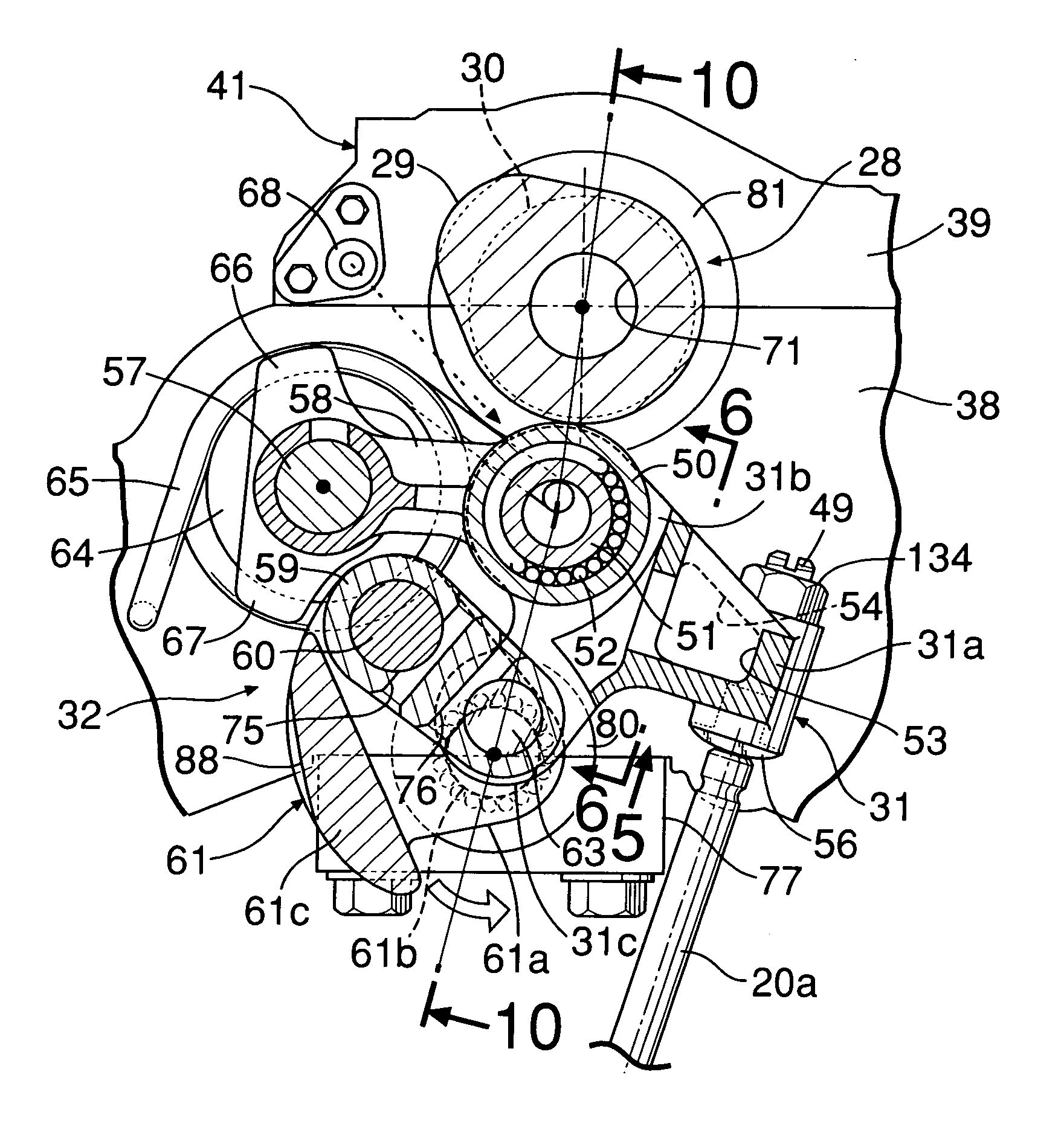
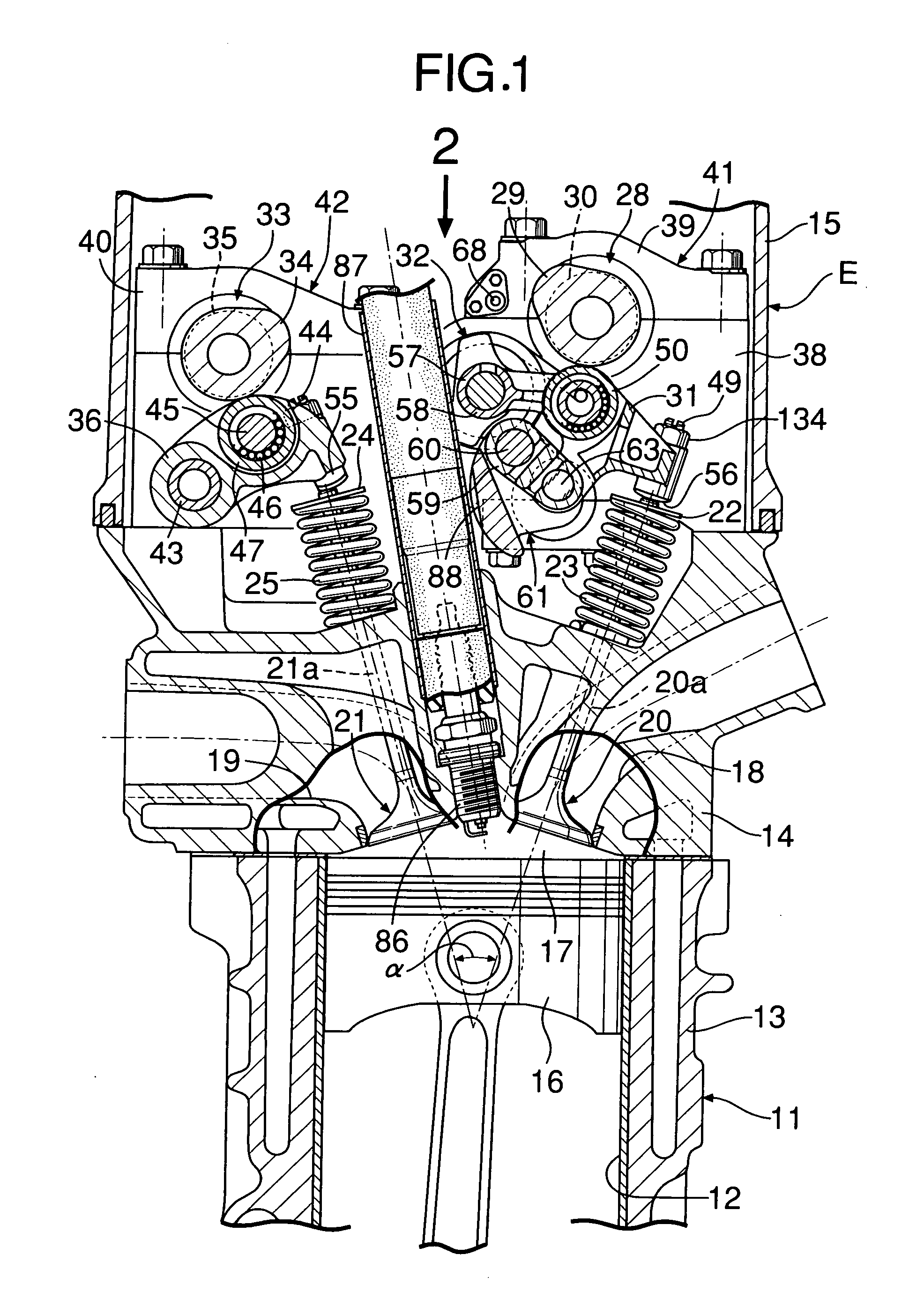
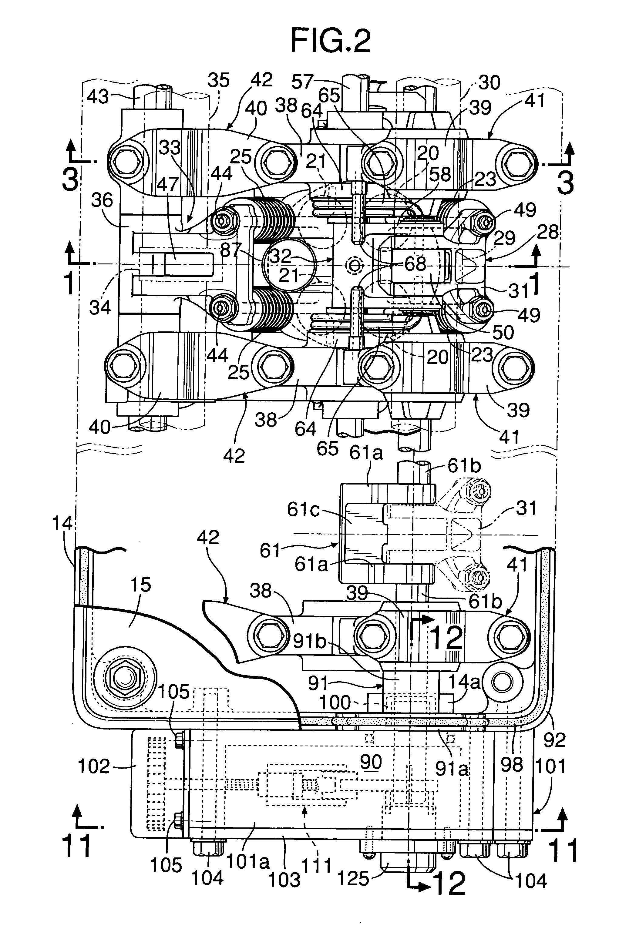
[0118] the present invention is described below with reference to FIGS. 14 to 16. One end of the control shaft 61 along the cylinder arrangement direction, that is, the journal portion 61b at one end along the cylinder arrangement direction among a plurality of journal portions 61b . . . provided on the control shaft 61 is protruded out of the sidewall of the head cover 15 of the engine body 11 and inserted into a casing 140 attached to the outer faces of the sidewalls of the cylinder head 14 and head cover 15 so as to be repeatedly attached and detached.

[0119] The casing 140 is constituted by a casing body 141 and a lid member 142 fastened to the casing body 141. The casing body 141 is formed into the shape of a box opening on a side opposite to the cylinder head 14. The lid member 142 covers the casing body 141 from a side opposite to the cylinder head 14. The casing 140 is attached to the outer faces of the sidewalls of the cylinder head 14 and the head cover 15 by a plurality of...

first embodiment

[0127] Therefore, the lubricating oil scattered in the head cover 15 and the lubricating oil leaked from the bearing of the intake-side cam shaft 30 (refer to first embodiment) are stored in the oil reservoir 151, and introduced into the casing 140 from the oil path 152 of the journal portion 61b under the oil level in the oil reservoir 151. The lubricating oil dripped from the journal portion 61b lubricates the screwed portion between the screw shaft 114 and the nut member 115. Moreover, the lubricating oil dripped to the lower portion in the casing 140 is returned from a drain hole 153 formed at the lower portion of the casing body 141 in the casing 140 to the cylinder head 14 side.

[0128] According to the second embodiment, the lubricating oil scattered in the head cover 15 and the oil leaked from the bearing of the intake-side cam shaft 30 are stored in the oil reservoir 151, and supplied to the casing 140 side by gravitation. Therefore, additional energy is not required to suppl...


PUM


Abstract

A drive of a variable valve lift mechanism for driving a control shaft controlling a variable valve lift mechanism provided between an engine valve and an engine valve operating cam in order to change lift amount of the engine valve, comprises: a rotational force generating actuator; power conversion means for converting a rotational force of the rotational force generating actuator into a pivoting force of the control shaft; and a casing containing the power conversion means with the rotational force generating actuator coupled to an outer face of the casing. One end of the control shaft protrudes outward from one side of an engine body. The casing into which one end of the control shaft is inserted is attached to the one side of the engine body through fixing means which can be repeatedly attached and detached. Thus, it is possible to avoid the engine body from being complex and improve maintainability.

Description

RELATED APPLICATION DATA [0001] The Japanese priority application Nos. 2003-426070 and 2003-49347 upon which the present application is based are hereby incorporated in their entirety herein by reference. BACKGROUND OF THE INVENTION [0002] 1. Field of the Invention [0003] The present invention relates to a drive of a variable valve lift mechanism for driving a control shaft controlling a variable valve lift mechanism provided between an engine valve and an engine valve operating cam in order to change lift amount of the engine valve. [0004] 2. Description of the Related Art [0005] In Japanese Patent Application Laid-open No. 2002-364317, the present applicant already proposed a valve operating system of an internal combustion engine having a variable valve lift mechanism for continuously varying the amount of lift (valve opening degree) of an intake valve serving as an engine valve. This engine valve operating system is constituted so as to rotation-drive a sector-shaped worm wheel ...

Claims


Application Information

Patent Timeline
IPC IPC(8): F01L13/00
CPCF01L1/18F01L1/185F01L1/267F01L2820/032F01L13/0026F01L2105/00F01L13/0015F01L2305/00
Inventor FUJII, NORIAKISAKAI, HISAOSHOJI, TADAHARUMARUYAMA, MOTOHIROFUJIMOTO, TOMOYAYONEKAWA, AKIYUKIMIZOROGI, TAKAHUMIYOSHIDA, KEIKO
Owner HONDA MOTOR CO LTD
Learn More