Backflow prevention valve

Inactive Publication Date: 2005-07-28
NIFCO INC
View PDF13 Cites 6 Cited by
  • Summary
  • Abstract
  • Description
  • Claims
  • Application Information

AI Technical Summary

Benefits of technology

[0014] In other words, in the backflow prevention valve of the present invention, a supporting guide device is provided for supporting and guiding the valve member to be movable for opening and closing movements. The supporting guide device is provided between an inner peripheral surface of the case member and an outer peripheral surface of the valve member. The supporting guide device may be formed of a guide arm provided in the valve member and inserted in a guide groove provided on the peripheral surface of the liquid inflow pipe. Therefore, the liquid inflow pipe has a smooth inner peripheral surface without unevenness.
[00

Problems solved by technology

However, in the conventional backflow prevention valve, the valve member e does not move smoothly when the fuel is supplied.
Also, due to the turbul

Method used


Image

  • Backflow prevention valve
  • Backflow prevention valve
  • Backflow prevention valve

Examples


first embodiment

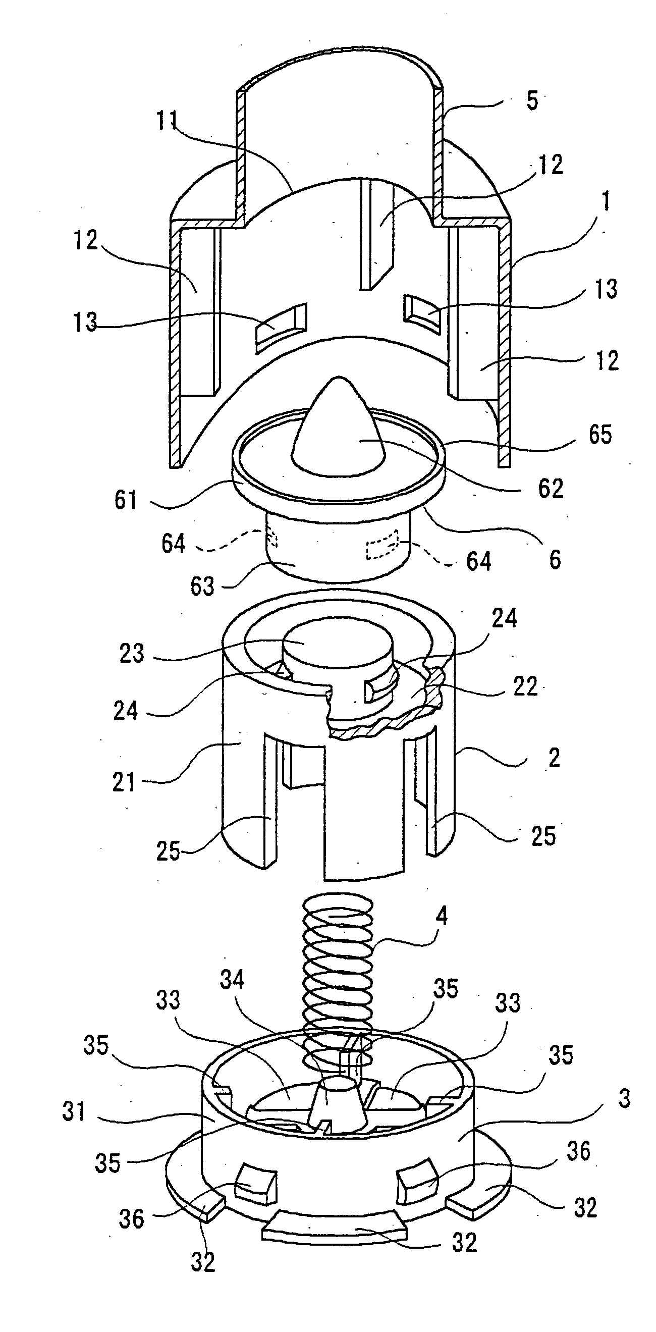
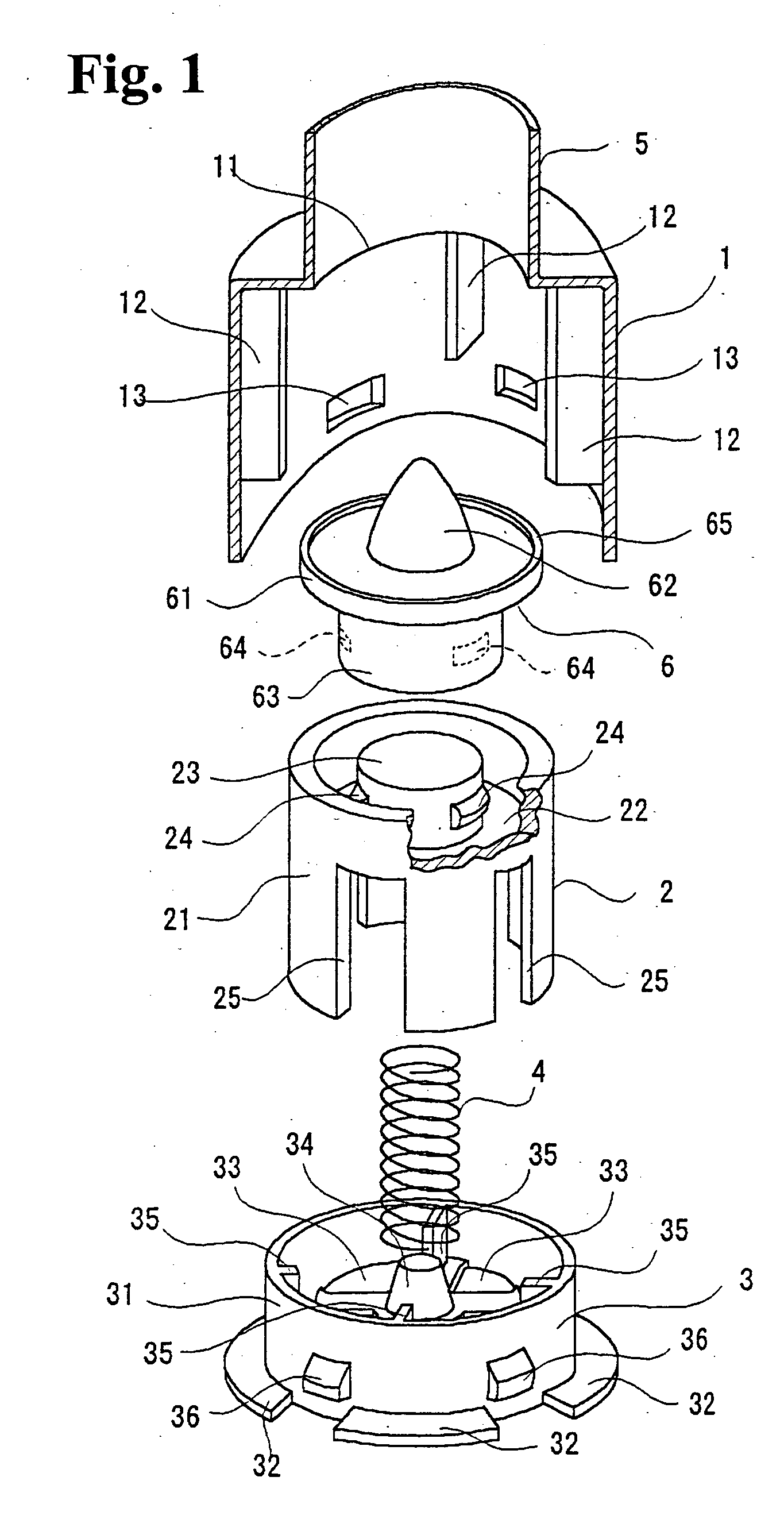
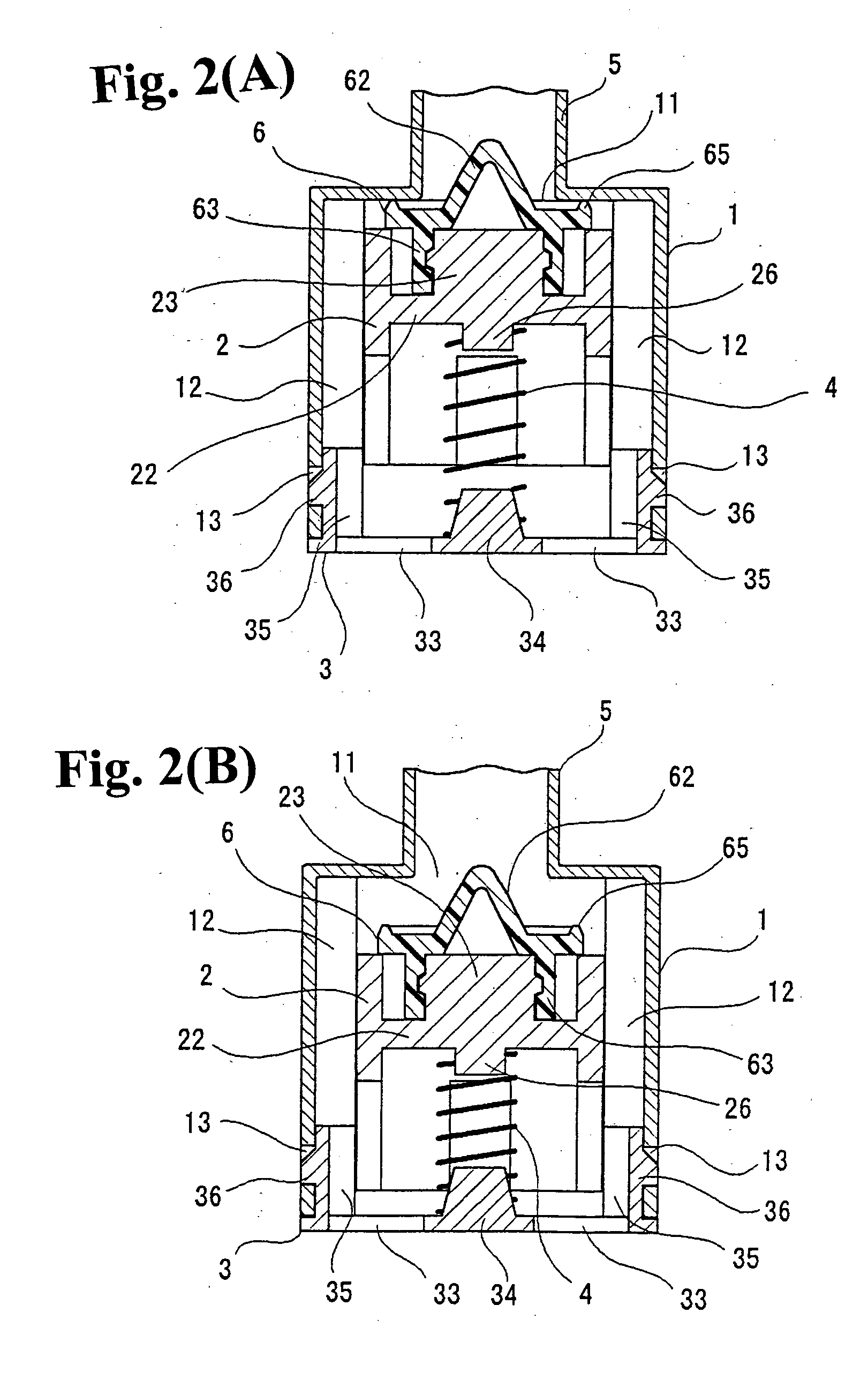
[0026]FIGS. 1 and 2(A), 2(B) show a backflow prevention valve according to the present invention. As shown in FIG. 1, the backflow prevention valve includes a cylindrical case member 1; a valve member 2 disposed inside the case main member 1 to be movable along an axial direction; a coil spring (urging device) 4 for urging the valve member 2; and a covering member 3 for closing a lower end of the case member 1.

[0027] A ring-shape wall plate is provided at an upper end of the case member 1, and a circular inflow opening 11 is provided at a center of the wall plate. A liquid inflow pipe 5 with a smaller diameter than that of the case member 1 is integrally connected to the inflow opening 11 from outside. Four ribs 12 (only three are shown in FIG. 1) are projected on an inner peripheral surface of the case member l along the axial direction at positions shifted by 90 degrees with each other. Furthermore, four engagement holes 13 (only two are shown in FIG. 1) are formed at a lower end ...

second embodiment

[0046] As shown in FIGS. 5(A) and 5(B), the valve member 10 is formed of a cylindrical main member 30 with an upper wall. Four guiding arms 20 are provided at a peripheral edge of an upper surface of the main member 30 at positions shifted by 90 degrees with each other. The cap member 9 and the sealing member 8 are fixed to the top surface of the main member 30 similar to the

[0047] As shown in FIGS. 6(A) and 6(B), the valve member 10 is housed to be movable inside the case member 1a in a state that each guiding arm 20 is projected outside through each hole 15. Each four guiding arm 20 projecting from the case member 1a is inserted and capable of sliding in each guiding slot 51 formed on the outer peripheral surface of the liquid inflow pipe 5.

[0048] In the backflow prevention valve, as shown in FIGS. 6(A) and 6(B), the guiding arms 20 slide inside the guiding slots 51 to support and guide the valve member 10, so that the opening and closing movements of the valve member 10 can be c...

third embodiment

[0050] In the backflow prevention valve of the third embodiment, the guiding arms 20 are inserted and capable of sliding in the guiding slots 51 through the holes 15 to support and guide the valve member 10. Alternatively, the holes 15 are formed in approximately the same sectional shape and size as the guiding arms 20, and the guiding arms slide inside the holes 15, thereby supporting and guiding the opening and closing movements of the valve member 10. In this case, the guiding slots 51 can be omitted. Further, it is possible to configure that the holes 15 and guiding slots 51 support and guide the opening and closing movements of the valve member 10 without omitting the guiding slots 51.

[0051] As described above, in the backflow prevention valves in the first, second, and third embodiments according to the present invention, the inner peripheral surface of the liquid inflow pipe 5 has a smooth surface without unevenness. As shown in the first and second embodiments, the supportin...


PUM


Abstract

A backflow prevention valve includes a cylindrical case member having a plurality of holes formed in an upper end at a periphery thereof, a valve member disposed in the case member to be movable in an axial direction thereof, an urging device disposed in the case member for urging the valve member upwardly, and a liquid inflow pipe extending outwardly from the case member. The valve member includes a sealing portion at an upper surface thereof for contacting a peripheral edge of an inflow opening to close the same, and a plurality of guiding arms provided on a peripheral edge of an upper surface of the valve member. The guiding arms are slidably disposed in the holes so that the valve member is supported and guided by the guiding arms passing through the holes.

Description

CROSS-REFERENCE TO RELATED APPLICATION [0001] This is a Divisional Application of Ser. No. 10 / 419,143 filed on Apr. 21, 2003.BACKGROUND OF THE INVENTION AND RELATED ART STATEMENT [0002] The present invention relates to a backflow prevention valve attached to a tip of a fuel supply pipe for supplying fuel to a fuel tank of an automobile. The backflow prevention valve is usually closed to prevent backflow of the fuel, so that when the automobile turns over or falls down, the fuel does not leak from the supply pipe. When the fuel is supplied to the fuel tank, a fuel liquid pressure opens the backflow prevention valve for the fueling. [0003] As shown in FIG. 7, a backflow prevention valve v is attached to a tip of a supply pipe p for supplying fuel into a fuel tank t of an automobile in order to prevent the fuel from leaking through the supply pipe p when the automobile turns over or falls down. [0004] As shown in FIGS. 8(A) and 8(B), a conventional backflow prevention valve has been di...

Claims


Application Information

Patent Timeline
IPC IPC(8): B60K15/04F02M37/00F16K15/02
CPCF16K15/026Y10T137/86372Y10T137/7937Y10T137/7938Y10T137/7925B60K15/04F16K15/063F16K15/025
Inventor TAKAHASHI, HIDEAKI
Owner NIFCO INC
Why Eureka
Try Eureka