Electric power tool

a technology of electric power tools and power tools, which is applied in the direction of electric generator control, dynamo-electric converter control, portable drilling machines, etc., can solve the problems of frame that can be worn on the back, cumbersome handling, and large weigh

Inactive Publication Date: 2005-07-28
ROBERT BOSCH GMBH
View PDF6 Cites 29 Cited by
  • Summary
  • Abstract
  • Description
  • Claims
  • Application Information

AI Technical Summary

Benefits of technology

[0005] It may moreover be advantageous here if the electric motor and at least one battery fitting it are combined in a drive unit that can be worn on the back and is accommodated interchangeably in the wearable unit. The drive unit may have two or more batteries combined with the electric motor, which are joined detachably to the drive unit and may be embodied as spare batteries. It may also be advantageous if the drive unit contains a control unit integrated with it for controlling the electric motor in particular, or the drawing of energy or the like. It may furthermore be advantageous if the drive unit has one spare holder for each battery. At least two existing batteries can advantageously be located in the drive unit and/or controlled in such a way that in operation of a driven tool connected to it, either parallel or sequential discharging takes place. In an advantageous refinement of the power tool, it has at least one additional electrical connec...

Problems solved by technology

This is an extreme hindrance and is problematic in use.
Another disadvantage is the frame...

Method used


Image

  • Electric power tool
  • Electric power tool
  • Electric power tool

Examples


Embodiment Construction

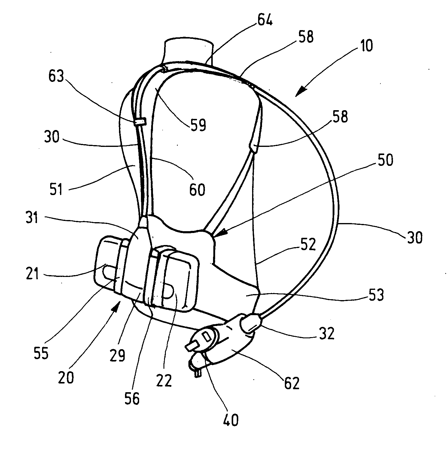
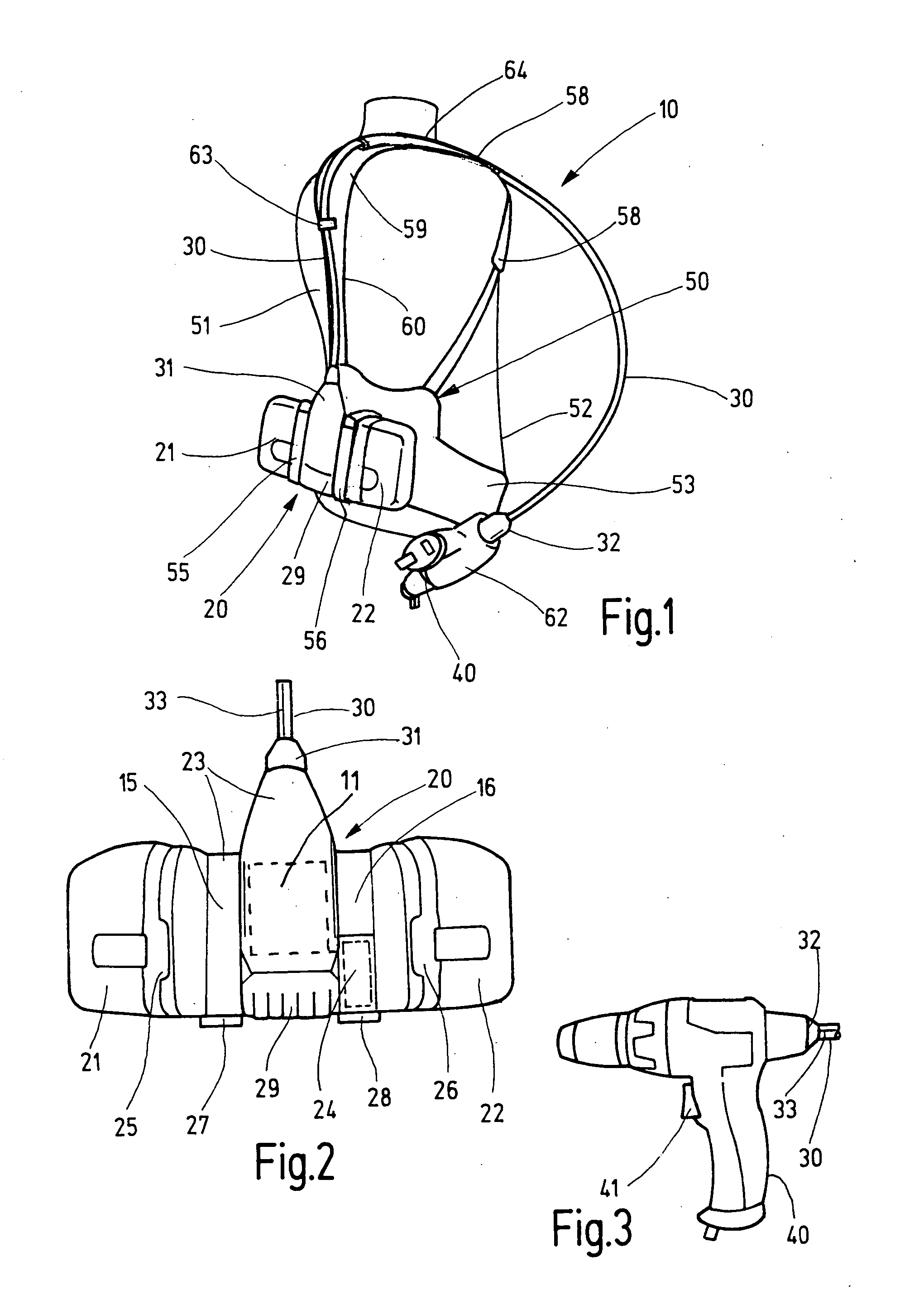
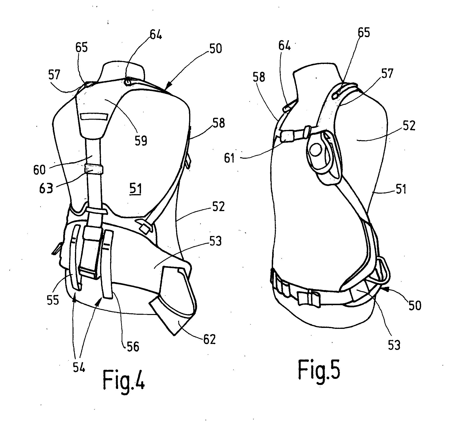
[0011] In the drawings, an electric power tool 10 is schematically shown which has a drive unit 20, a flexible shaft 30, and a virtually arbitrary driven tool 40, which can for instance be a screwdriver, hammer, saw, grinder, power drill, pruning shears, or the like and is connectable in a way to be driven to rotate to one end of the flexible shaft 30. In the exemplary embodiment shown, a screwdriver is provided for example as the driven tool 40, which as shown in FIG. 1 is connected to the flexible shaft 30. The drive unit 20 contains an electric motor 11, which is not further visible and which depending on the design has a gear downstream of it and can be powered by at least one battery that fits it, which in the exemplary embodiment shown are two batteries 21, 22 which are rechargeable. The electric motor, not visible, and at least one battery 21, 22 that fits it are combined in the drive unit 20 into a unit for use, to which the flexible shaft 30 is connected by the other end, d...


PUM

PropertyMeasurementUnit
Flexibilityaaaaaaaaaa

Abstract

An electric power tool (10) has at least one battery-powered electric motor, and the electric motor and the battery can be placed on the back of a user by means of a wearable unit (50). Via a flexible shaft (30), a driven tool (40) is driven by the electric motor. The wearable unit (50) has guide means (63 through 65), which engage the flexible shaft (30) in such a way that beginning at the back region of the user (52), this shaft is fixed in the shoulder region in such a way that it is secured against slipping off. This assures good guidance of the flexible shaft (30) and enables the user (52) to work ergonomically (FIG. 1).

Description

BACKGROUND OF THE INVENTION [0001] The invention is based on an electric power tool as generically defined by the preamble to claim 1. [0002] In a known electric power tool of this kind (German Utility Model DE 299 03 963 U1), a frame to be worn on the user's back is provided, which is held on the body of the user by means of supporting belts; the frame is intended to rest on the user's back. In the frame, an electric drive motor on the one hand and detached from it a battery pack are provided. The frame also includes a control unit for controlling the electric motor and the drawing of energy and so forth. The electric motor is located at the very bottom in the frame. The electric shaft extends laterally away from it, and on the free end of the shaft a driven tool is attached, in the form of pruning shears. The flexible shaft is extended along the user's side and under his arms to the front. This is an extreme hindrance and is problematic in use. Another disadvantage is the frame th...

Claims


Application Information

Patent Timeline
IPC IPC(8): B23B45/00B23B45/02B23B45/14B23Q9/00B25F3/00B25F5/00B25H3/00F16C1/00F16C1/06F16D67/00H02H7/06H02P9/00H02P11/00
CPCB25H3/006B23B45/005B23Q9/00F16C1/06
Inventor JENNI, DAVIDFREI, REMOBANDLI, CURDEGN
Owner ROBERT BOSCH GMBH
Why Eureka
Try Eureka