Apparatus and method for forming perforated band joist insulation

Inactive Publication Date: 2005-07-28
CERTAINTEED CORP
View PDF75 Cites 13 Cited by
  • Summary
  • Abstract
  • Description
  • Claims
  • Application Information

AI Technical Summary

Problems solved by technology

This process can be time consuming, creates scraps, and raises safety concerns.

Method used


Image

  • Apparatus and method for forming perforated band joist insulation
  • Apparatus and method for forming perforated band joist insulation
  • Apparatus and method for forming perforated band joist insulation

Examples


Embodiment Construction

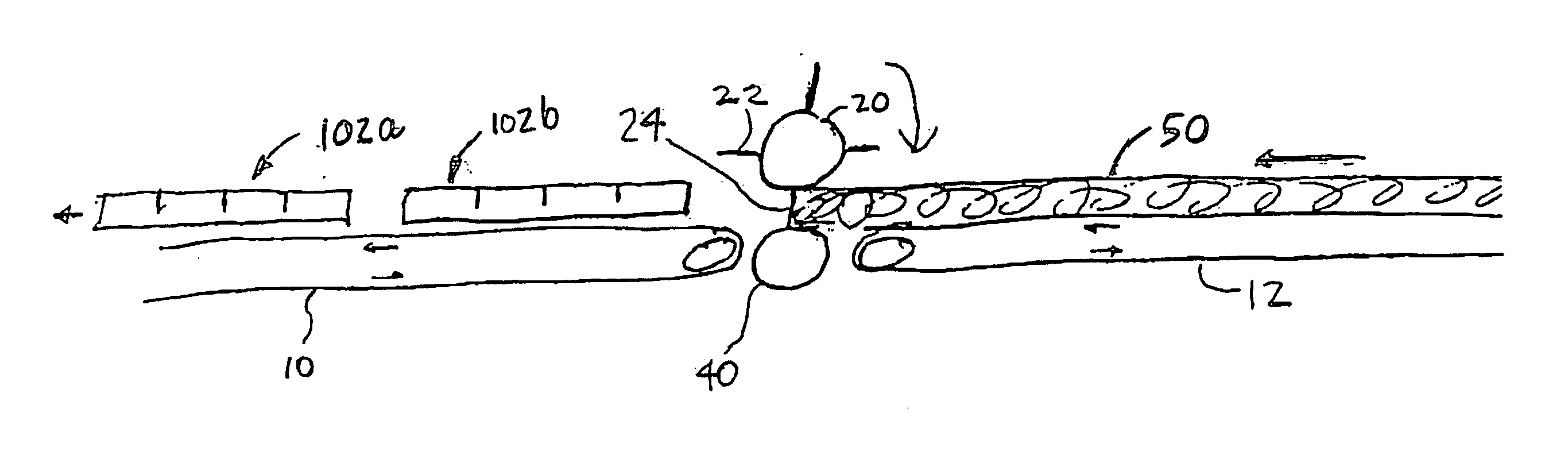
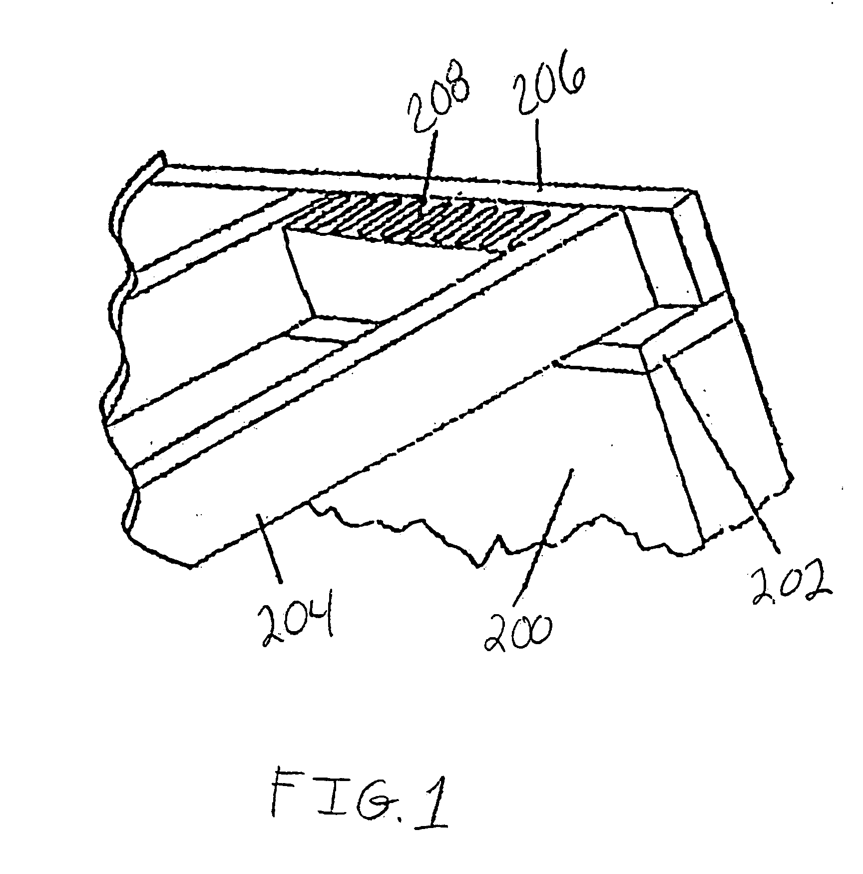
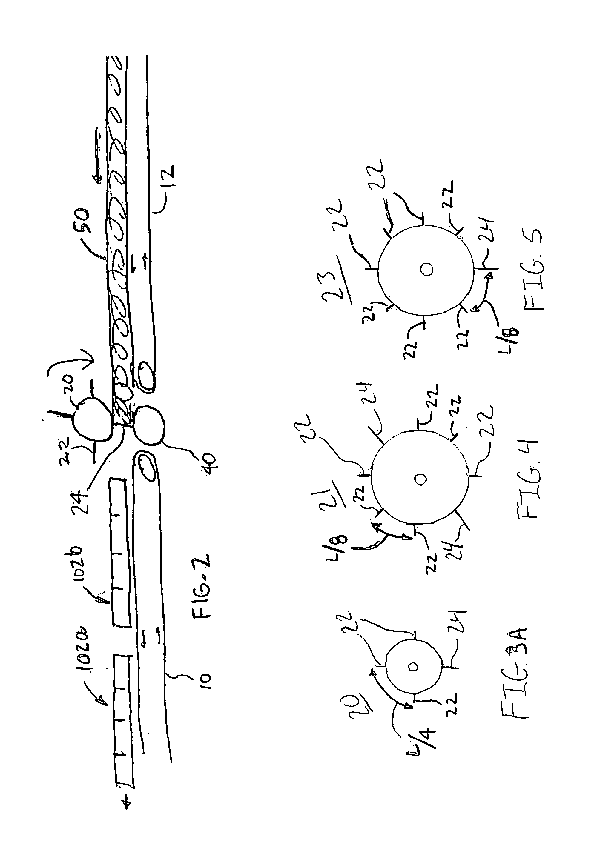
[0021] This description of the exemplary embodiments is intended to be read in connection with the accompanying drawings, which are to be considered part of the entire written description. In the description, relative terms such as “lower,”“upper,”“horizontal,”“vertical,”, “above,”“below,”“up,”“down,”“top” and “bottom” as well as derivative thereof (e.g., “horizontally,”“downwardly,”“upwardly,” etc.) should be construed to refer to the orientation as then described or as shown in the drawing under discussion. These relative terms are for convenience of description and do not require that the apparatus be constructed or operated in a particular orientation. Terms concerning attachments, coupling and the like, such as “connected” and “interconnected,” refer to a relationship wherein structures are secured or attached to one another either directly or indirectly through intervening structures, as well as both movable or rigid attachments or relationships, unless expressly described oth...


PUM

PropertyMeasurementUnit
Widthaaaaaaaaaa
Widthaaaaaaaaaa
Circumferenceaaaaaaaaaa

Abstract

An insulation manufacturing apparatus includes a conveyor for conveying the insulation, a rotary die cutting cylinder having at least one slicing or perfing rule and at least one cutting rule, and an anvil cooperative with the rotary die cutting cylinder for partially slicing, perforating or severing the insulation. The rotary die cutting cylinder is located along a path of the conveyor.

Description

FIELD OF THE INVENTION [0001] The present invention relates to building insulation, and more particularly to apparatuses and methods for manufacturing insulation batts for band joist spaces. BACKGROUND OF THE INVENTION [0002] Insulation blankets formed from mineral fibers, very often fiberglass, are well known and have long been used for building insulation. Generally, the insulation blankets are packaged in sizes conforming to standard sizes of structural framework building cavities formed by wall studs, roof rafters, and the like. For example, the typical spacing between many framing members used in residential houses is approximately 14½ inches or 22½ inches. Therefore, insulation blankets are normally manufactured to be about 15 inches or 23 inches in width so that they can be slightly compressed to fit snugly into the 14½ inch or 22½ inch spacing. [0003] Referring to FIG. 1, in housing construction, there are usually multiple band joist spaces which require insulation. As shown...

Claims


Application Information

Patent Timeline
IPC IPC(8): B26D1/40B26D9/00B26F1/20B26F3/00E04B1/74E04B1/76
CPCB26D1/40B26D9/00E04B2001/741E04B1/7662B26F1/20Y10T83/4838Y10T225/35Y10T225/12Y10T225/16
Inventor LEMBO, MICHAEL J.TOAS, MURRAY S.BROWN, ERICNILSSON, ERIC
Owner CERTAINTEED CORP
Why Eureka
Try Eureka