Feeder verification with a camera

a technology of camera and feeder, applied in the field of feeder verification with a camera, can solve the problems of high probability of component loading error, high number of defective printed circuit boards, and error in the placement of components on the board, and achieve the effect of simple procedure, safe and fas

Inactive Publication Date: 2005-07-28
VALOR DENMARK AS
View PDF11 Cites 34 Cited by
  • Summary
  • Abstract
  • Description
  • Claims
  • Application Information

AI Technical Summary

Benefits of technology

[0014] The equipment necessary for post-mounting a system according to the invention, where the method according to the invention may be implemented, is cheap and implies mainly one or several low cost cameras, some cabling, a programmed computer and an image analysis program. Therefore, such a system is highly attractive. Another advantage is the fact that the method according to the invention is applicable for several types of machines. It may be applied with machines, where the feeder slots are mounted on a stationary platform and where the components are picked-up by a moving pick-up. It may also be applied for machines, where the pick-up is stationary and where the platform with the feeder slots is displaceable.
[0037] Measuring distances and assigning coordinates to the slots and feeders can be used for a further improvement of the invention. In this case, the feeder type may be identified, for example by measuring the width of the feeder. This feature further reduces the risk for faults.

Problems solved by technology

Any error in the arrangement can cause a corresponding error in the placement of components on the board.
In a high volume, low mix manufacturing environment, a component loading error can produce a high number of defective printed circuit boards in a short period of time.
In a low volume, high mix environment the chance of component loading error increases because of frequent feeder manipulation for product change over.
Often, component placement machines are not born with sufficient control mechanisms to assure the feeding of correct components as desired by the user of these types of machines.
Firstly, this system is only suited for machines with sufficient space for mounting of a camera on the moving pick-up mechanism.
For a system integrated in a special machine, this is adaptable; however, several existing feeder machines do not have space at the pick-up region for mount of an ID.
Therefore, this system is not suited for post-mounting.
Thirdly, this system utilizes the machine information of the slot positions.
As the machine is born with the control system, this utilizing is possible; however, such position information is usually not available for post-mounted systems.
Fourthly, the procedure is performed before the start of the machine and in case of determined mistakes repeated before the start of the machine.
Thereby, expensive time is wasted before the production start.
This adds up to a long time before the machine is ready for operation.
Such a control system is only suitable for existing machines, where the table is moveable while the pick up is stationary, because in many existing machines with movable pick-up systems, not enough space is left on the pick up for mounting a scanner on the pick-up.
This system as described in U.S. Pat. No. 6,027,019 has another disadvantage in not being able to detect feeders with wrong components before the machine is started.
If a component is wrong, expensive time is wasted until the machine is stopped and rearranged.
A third disadvantage has also been observed for this system.
As the table is moved, problems with reading of the feeder ID may occur in situations where a component from a special feeder is picked up from one edge of the feeder such that the feeder position is different than if the component would be picked up from the centre of the feeder.
However, also this system has a drawback in not being able to prevent a misplacement of the transponder.
The latter is due to the fact that feeders may be rather slim with the result of a hardly discernible correct position of two adjacent feeder positions in the platform.
For existing machines, no control solution has hitherto been proposed for taking into account the situation of the so-called splicing when a feeder only has a few components left on a tape.
However, no system has hitherto been provided to control whether a tape with correct components has been spliced to the tape with the remaining few components.

Method used


Image

  • Feeder verification with a camera
  • Feeder verification with a camera
  • Feeder verification with a camera

Examples


Embodiment Construction

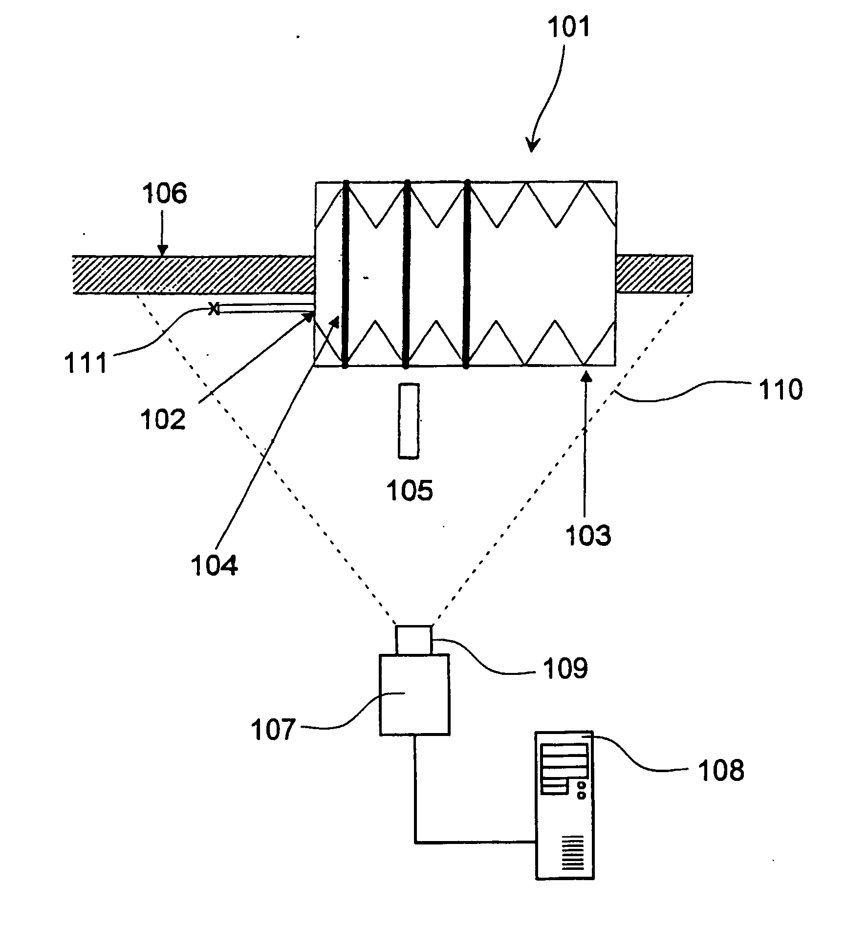
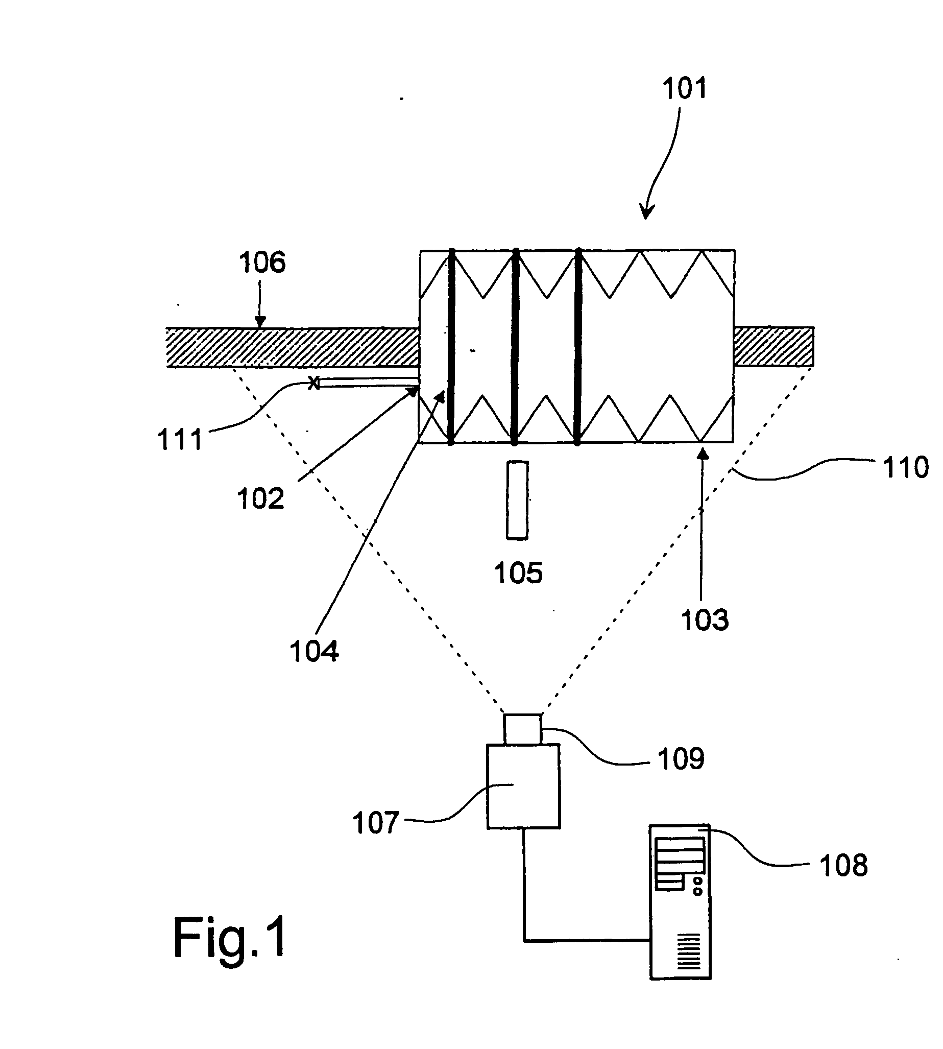
[0047] In FIG. 1, a placement machine 101 is illustrated having a platform 102, on which a number of slots 103 are located. Into each slot 103, a feeder 104 may be placed. Certain feeder 104 types may extend into several slots 103. The platform 102 is displaced relatively to the component pick up arm 105 for picking up components from different slots 103. Alternatively, the pick up arm 105 may be displaced with respect to the platform 102.

[0048] Each feeder 104 is provided with an identification marker, feeder ID, for example a bar code label that is designed to be readable by an appropriate scanner. According to the invention, the feeder ID is imaged by a camera 107 and analyzed in a computer 108 by an image analysis computer program. By using a camera 107 according to the invention, the feeder marker may be different from a bar-code and may contain additional information about the feeder, and eventually information about the contained type of components.

[0049] The camera 107 ima...


PUM


Abstract

Method for component verification during operation of a component placement machine (101) having a series of feeder slots (103) for holding component feeders (104) with feeder markers, each feeder marker carrying a unique feeder ID, wherein each feeder slot (103) has a unique slot ID (208). On an image taken with a camera of the feeder slots, image analysis is performed to check whether the actual feeders in the slots corresponds to those feeders that are intended to be placed in these slots.

Description

FIELD OF THE INVENTION [0001] The present invention relates to the monitoring of the configuration of component feeders on a component placement machine, for example for electronic components. BACKGROUND OF THE INVENTION [0002] For electronic board assembly, automated component placement can reach very high speed up to tens of thousands of surface mounts of components per hour. These components are typically supplied by component vendors as taped reels of components which are loaded onto individual feeders which then are mounted in corresponding feeder slots on the machine. These reels of components may be loaded onto the feeders at a special loading unit, for example in a stock room, after which the loaded feeders are placed in the feeder slots. [0003] Component placement machines can have more than 100 feeder slots each accessible by a picking mechanism that picks individual components from the feeders in the slots and places them in particular predetermined locations on a printed...

Claims


Application Information

Patent Timeline
Patent Type & Authority Applications(United States)
IPC IPC(8): G06T1/00H05K13/02H05K13/04H05K13/08
CPCH05K13/08H05K13/0452H05K13/0417H05K13/087H05K13/081
Inventor BYSKOV, KURTMAERKEDAHL, HENNING
Owner VALOR DENMARK AS
Why Eureka
Try Eureka