
Voting method and apparatus

Inactive Publication Date: 2005-07-28
OPENSHAW MARK II +2
View PDF15 Cites 34 Cited by
  • Summary
  • Abstract
  • Description
  • Claims
  • Application Information

AI Technical Summary

Benefits of technology

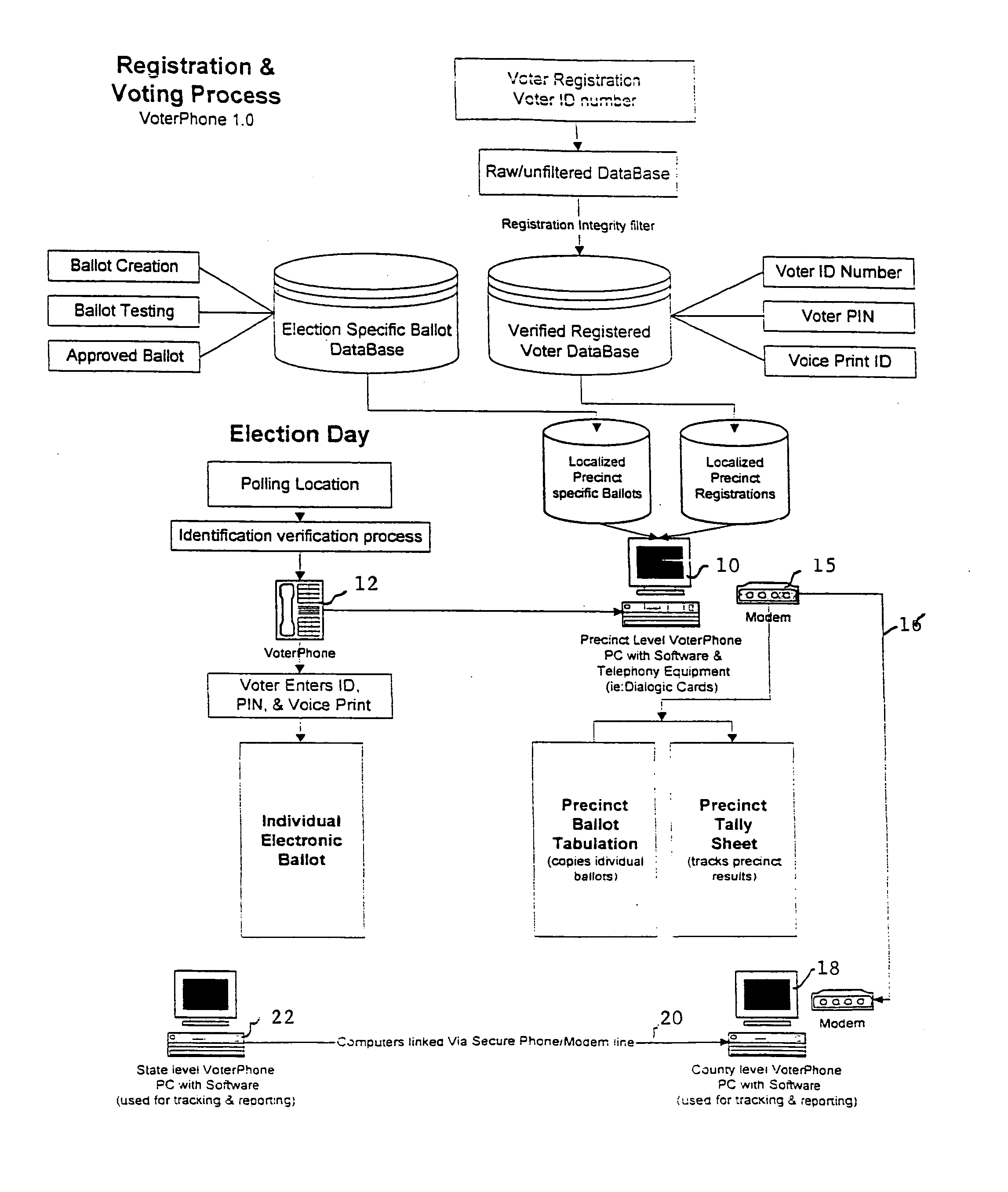
[0020] This automated telephone system first asks the votes to enter their registration number, and then their voter access number. The computer scans the combination of the RN and VAN numbers and, if correct, opens an Election Direct Program, which is inputted into the computer. (The voice activated system, compares the voice print with the stored voice print before activating the Election Direct Program). The Election Direct Program then assigns the voter a pre-approved random electronic ballot, which is read by the computer. The voter selections are randomized to avoid the need of a secure voting booth as observers would not be able to detect the voters' preferences by observing the touchtone selections. This allows more voter telephone stations to be added by an election judge to handle problems when large crowds of voters show up simultaneously and additional isolated voting booths cannot be installed.
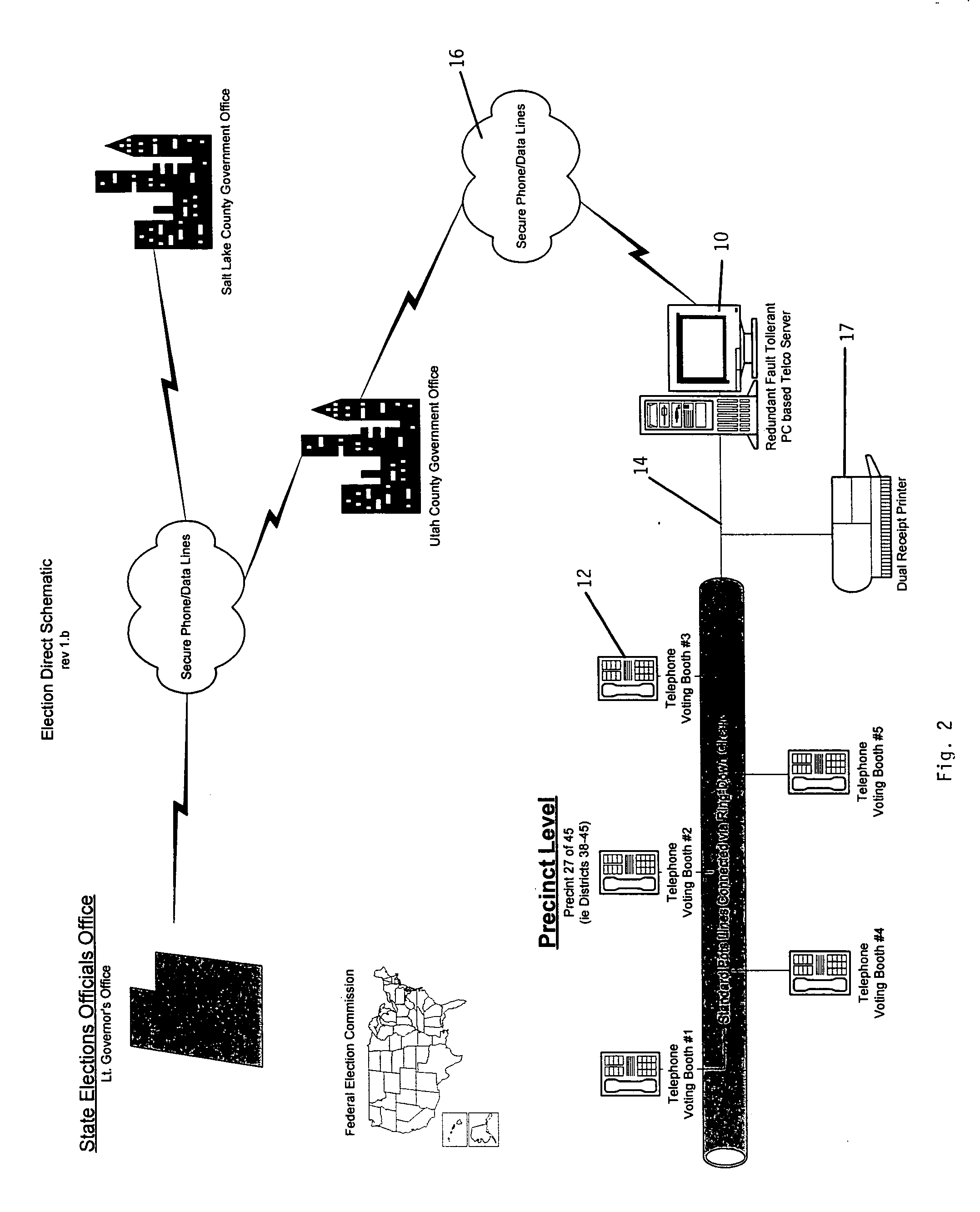
[0048] To insure security of the voting process, all information transmitted within the Election Direct System is on a Virtual Private Network (VPN) in communication with a precinct tabulating personal computer employing the Election Direct System data entry software. This eliminates any opportunity for external hackers or crackers to enter the system. Only the combination of an approved registration number (Social Security Number) and a valid unique voter access number (VAN) will engage the Election Direct System. Codes on each electronic ballot identify the location of the precinct and the county, but are never connected to the registration or voter access number. This allows election officials to know who voted in an election, but prevents anyone from knowing how someone voted. It allows the anonymous results to be accurately counted and properly stored.
[0049] Although other voice activated voter input systems may be employed, a conventional touchtone telephone is preferred for instructing and requesting a voter to enter their preferences, because of its familiarity with most voters. This eliminates the need for extensive usage instruction, while maintaining high voter accuracy. Touchtone telephones are also inexpensive, and can be employed with or without a booth to enter voter preferences as the key entry of votes is random and cannot be detected without overhearing the voter instructions. These telephones can also employ sound amplifiers for the hearing impaired.
[0056] The mobile VPC central processing terminals thus provide a convenient voting terminal for voters. They are connected to a centralized state or district receiving computer to verify the validity of the voting transactions. Thus, fraudulent votes are minimized. They also allow local election judges to identify voters having trouble voting and to timely intercede to insure that the voter has properly voted.
[0057] Mobile VPC terminals allow election judges to maintain better supervision of the voting process. They may add additional voting telephone stations, where needed to provide great flexibility to deal with larger voter turnouts, or remove the same to prevent tampering. They are moved around and added within the voter precinct to accommodate voters' needs.
[0058] The present invention thus provides a secure, inexpensive, highly accurate and convenient mobile VPC central processing terminal and voting system, which is readily adapted to provide for a voters' needs to participate in the election process. It incorporates a voter receipt tracking standby system for voter audits and is readily adapted for use with different languages. It can also be adapted to take various product marketing surveys, trademark and brand name comparison surveys, etc., when not in use for official and unofficial elections.

Problems solved by technology

More reliable and efficient technology is available, but state and local governments have been reluctant to invest because of cost.
While these systems are advanced and state of the art, they are not the answer to America's voting dilemma.
Many don't have a home with a telephone, nor are these public access lines secure to prevent tampering.
These systems are also expensive, because of the security and specialized equipment required to safeguard the votes.

Method used


Image

  • Voting method and apparatus
  • Voting method and apparatus
  • Voting method and apparatus

Examples


Embodiment Construction

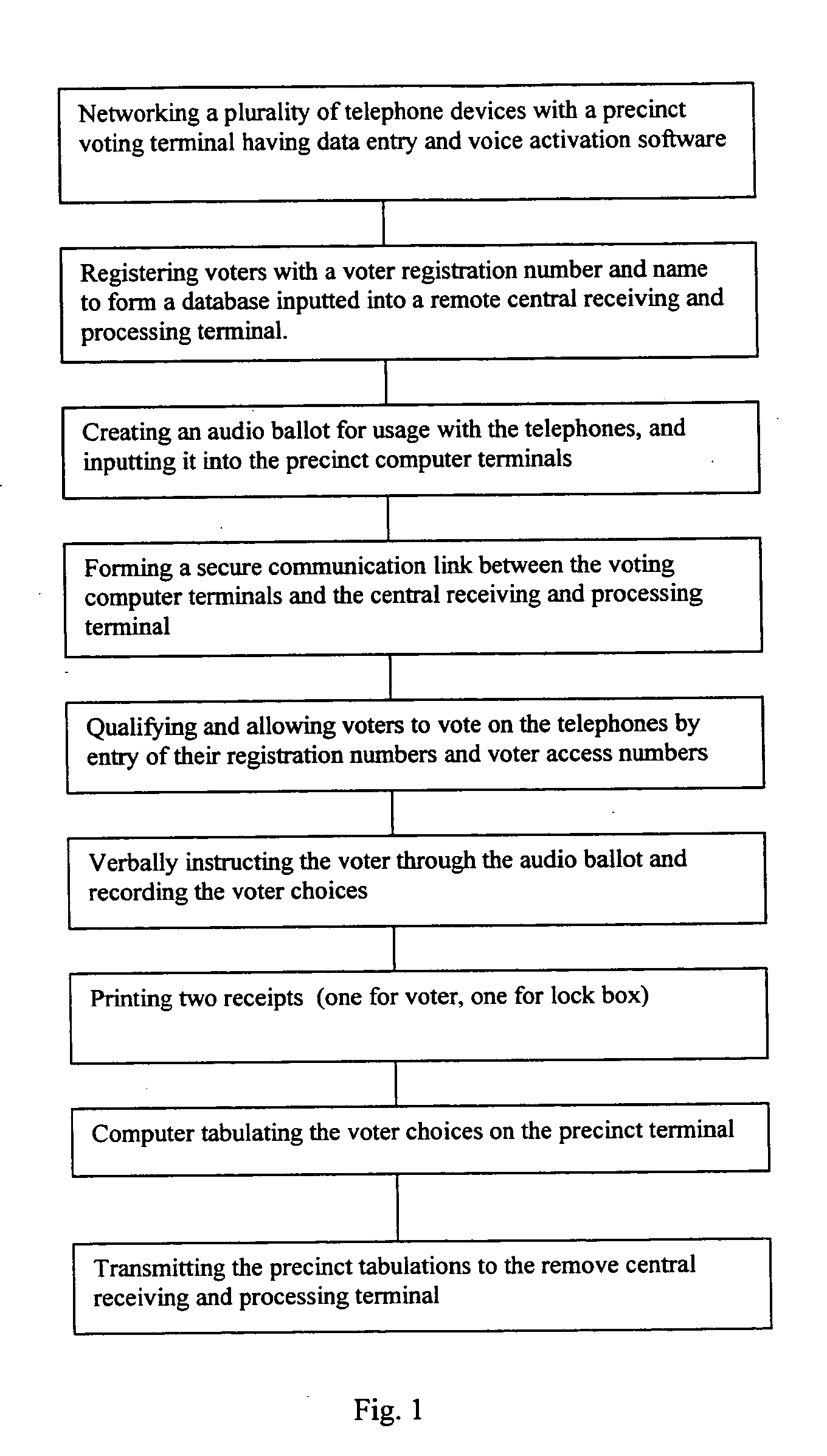
[0063]FIG. 1 is a flow chart of applicant's preferred method of voting. The voting method employs interconnected precinct voting terminals having data entry and voice activation software with a plurality of automated touchtone telephone devices. These touchtone telephones have microphones, receivers, transmitters and receivers, and entry keypads. They are interconnected with the precinct voting terminals via a virtual private network. Voters are then registered in accordance with election laws and assigned a voter registration number. Their names and voter registration numbers are then inputted into a database stored in a remote central receiving and processing terminal.

[0064] Next, an audio ballot is created suitable for transmission over a telephone, and is inputted into a database including audio ballot instructions required in each respective precinct computer terminal. A secure communication link between the precinct voting computer terminal and the central receiving and proce...


PUM


Abstract

The present specification discloses a secure, inexpensive, highly accurate and convenient mobile voter precinct tabulating computer terminal operably associated with touchtone telephones on a virtual private network, which employs audio ballot questionnaire software to solicit and record voter preferences, generates dual voter receipts listing each voter's choices for manual audits and recounts, and then transmits voter tabulations to a remote central processing terminal for final certification.

Description

RELATED APPLICATIONS [0001] This application is a continuation-in-part application of the original patent application entitled “Voting Method and Apparatus” filed Jan. 18, 2001, Ser. No. 09 / 764,969.BACKGROUND OF THE INVENTION [0002] 1. Field of Invention [0003] The present invention relates to voting terminals and a method of using the same. In particular, it relates to a highly accurate inexpensive easy to use voting terminal employing telephones attached to a secure line interacting with an isolated voice responsive election computer adapted for tabulating votes for use with various types of elections. [0004] 2. Description of Related Art [0005] Various voting terminals and voting systems are known. Willard, U.S. Pat. No. 5,821,508 describes an audio ballot system for voters who are blind, illiterate, or conversant in a foreign language employing complicated speech input and communication devices. Gordon et al., U.S. Pat. No. 3,766,541 describes a voting machine employing a series...

Claims


Application Information

Patent Timeline
IPC IPC(8): G07C13/00
CPCG07C13/00
Inventor OPENSHAW, MARK IIPAYNE, GUY DAVIDWALZ, JOHN ROBERT
Owner OPENSHAW MARK II
Learn More