
Photoconductor charging device and image forming device using same

a charging device and photoconductor technology, applied in the field of electroctrophotographic image forming devices, can solve the problems of reducing the electrical characteristics of the photoconductor, affecting the living body, increasing the cost and production of larger noises, etc., and achieving the effect of reducing the adhesion of foreign materials to the electrode pla

Inactive Publication Date: 2005-07-28
RICOH KK
View PDF3 Cites 2 Cited by
  • Summary
  • Abstract
  • Description
  • Claims
  • Application Information

AI Technical Summary

Benefits of technology

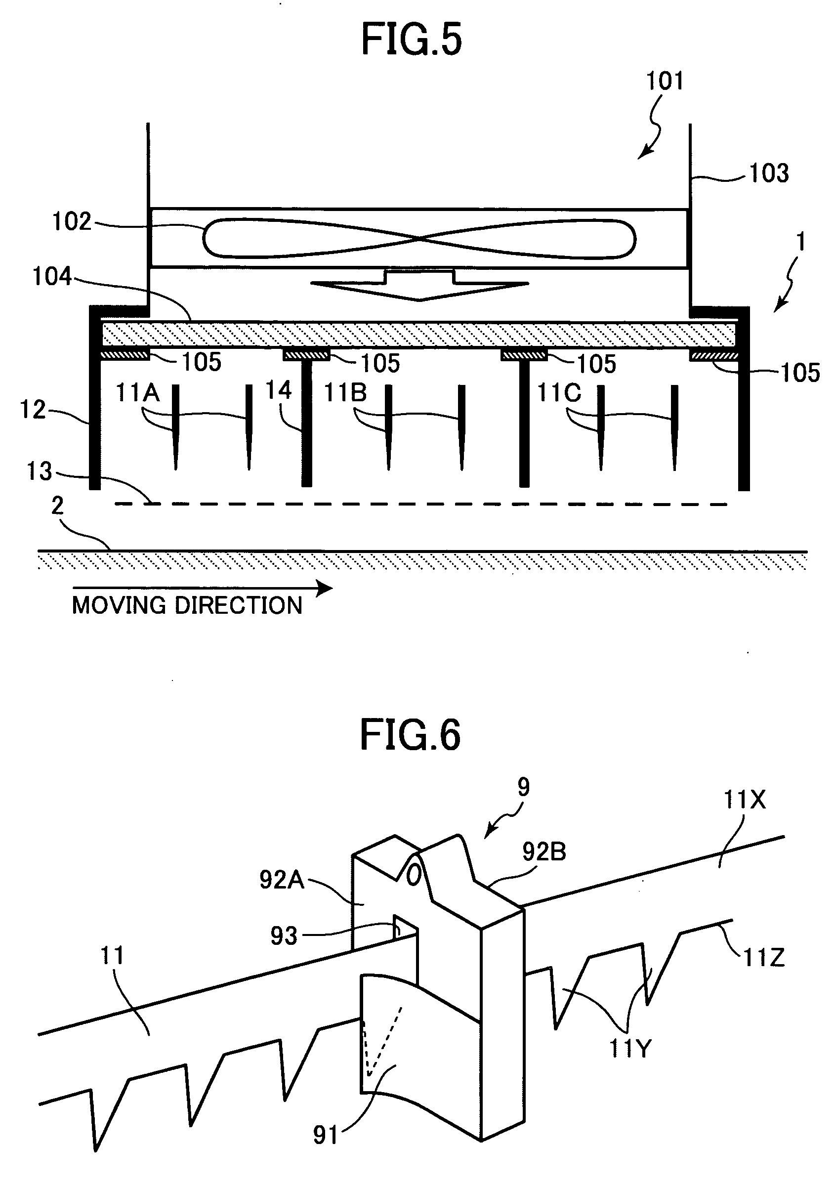
[0015] It is further desirable that a filter be additionally provided in order to prevent foreign materials contained in air from entering into a space where each of the first, second, and third saw-tooth electrode sections is disposed.

Problems solved by technology

Electrophotographic technology using dry toner is applied to various kinds of image forming devices such as copying machine, printer or facsimile machine due to inexpensive page cost.
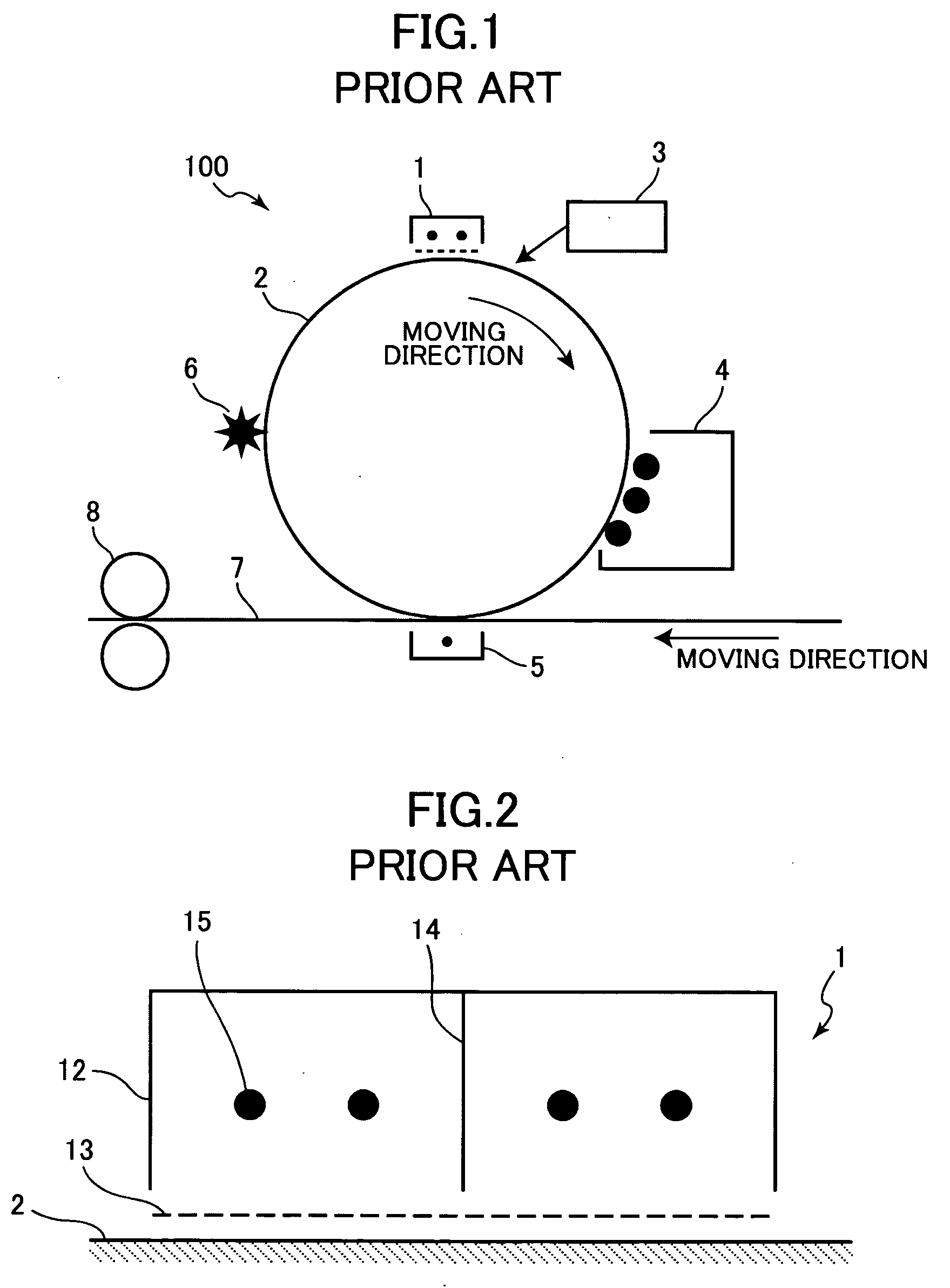
However, corona discharges that generate negative polarity ions produce a great deal of ozone, which degrades electrical characteristics of the photoconductor 2 and also exerts bad influence upon living bodies.
This, however, invites increase of cost and production of larger noises In order to solve the above-described problems, Japanese Patent Application Publication No. 63-15272 proposes a charging device in which a saw-tooth shaped electrode is used in place of the wire electrode.
However, the corona discharges generated at the tip end portions of the saw-tooth electrodes attract foreign materials, such as dust, toner, or paper dust floating in the air.
Once the foreign materials are adhered to the tip end portion of the saw-tooth electrode, the corona discharge tends to be unstable, causing the image to degrade.
However, if the voltage applied to the saw-tooth shaped electrode becomes too high, the corona discharge proceeds to a spark discharge, and thus the photoconductor is damaged.
However, due to the sharpness of the tip end portion of the saw-tooth electrode, the cleaning member is easily damaged and so the cleaning effect is lowered.

Method used


Image

  • Photoconductor charging device and image forming device using same
  • Photoconductor charging device and image forming device using same
  • Photoconductor charging device and image forming device using same

Examples


experiment 1

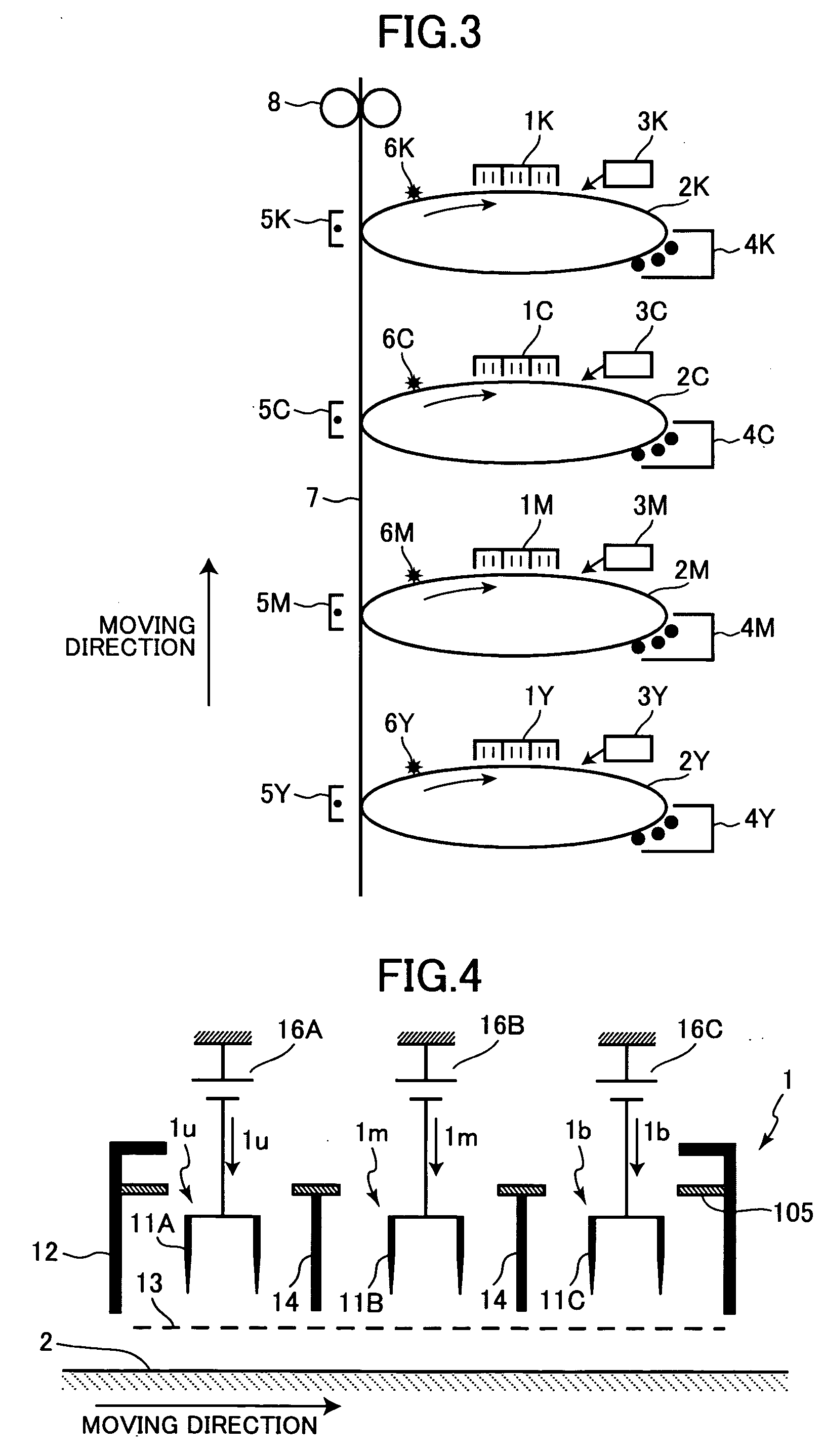
[0041] In order to provide a reference used as a basis for comparison, unitary current of 1.39 μA / mm is equally applied to the three pairs of the electrode plates 11A, 11B, and 11C which are set in the upstream side 1u, center portion 1m, and the downstream side 1b, respectively. As a result of experiment, generation of the black strips was recognized in the tip end portion of the saw-tooth electrode after about 35000 rotations of the photoconductor 2. Investigation of the black strips with an electronic microscope revealed that the materials forming the black strips are discolored foreign materials including dusts, toner, and paper dust as contained in the air. To generate corona discharges using the electrodes formed with the black stripes, a higher voltage needs to be applied to the electrodes than the normal voltage. Because, in the foreign material adhered condition, the corona discharges are unlikely to occur if the voltage applied to the electrode is maintained at the normal ...

experiment 2

[0042] Unitary current of 2.93 μA / mm is applied to the center electrode plates 11B and unitary current of 0.63 μA / mm is applied to each of the upstream-side and downstream-side electrode plates 11A and 11C. That is, the unitary current set to flow in the center electrode plates 1B is 4.7 times as much as the unitary current set to flow in the upstream-side and downstream-side electrode plates 1A and 1C. In this condition, adhesion of the foreign materials to the tip end portion of the saw-tooth electrode 11 was recognized after about 20000 rotations of the photoconductor 2. The corona discharge voltage was increased in due course and was proceeded to a spark discharge.

experiment 3

[0043] Unitary current Im for the electrode plates 11B disposed in the center portion was set to 1.3 to 3.0 times as much as unitary current Iu or Ib for the electrode plates 11A and 11C disposed in the upstream and downstream sides. Specifically, unitary current of 1.67 μA / mm was applied to the center electrode plates 11B and unitary current of 1.25 μA / mm was applied to the upstream-side and downstream-side electrode plates 11A and 11C. That is, the unitary current set to flow in the center electrode plates 1B is 1.3 times as much as the unitary current set to flow in the upstream-side and downstream-side electrode plates 1A and 1C. In this condition, adhesion of the foreign materials to the tip end portion of the saw-tooth electrodes 11 was not recognized until the photoconductor 2 was rotated about 40000 times.


PUM


Abstract

In a charging device having saw-tooth electrodes for generating corona discharges, an amount of dust, toner, or paper dust attached to the tip end portions of saw-tooth electrodes is reduced. First to third pairs of saw-tooth electrode plates are disposed in a side-by-side fashion along the periphery of a photosensitive drum in which the first pair is disposed at an upstream side with respect to a direction in which the photosensitive drum rotates, the third pair at a downstream side, and the second pair at a central portion between the remaining two. A current flowing per a unit length of the second pair is set to 1.3 to 3 times as much as a current flowing per a unit length of each of the first and third pairs. The currents flowing per a unit length of the first and third pairs are set to be equal to each other.

Description

BACKGROUND OF THE INVENTION [0001] 1. Field of the Invention [0002] The present invention relates to an electrophotographic image forming device such as copying machine, printer, or facsimile machine. More particularly, the invention relates to a charging device for uniformly charging a photoconductor using a corona discharge. [0003] 2. Description of the Related Art [0004] Electrophotographic technology using dry toner is applied to various kinds of image forming devices such as copying machine, printer or facsimile machine due to inexpensive page cost. [0005]FIG. 1 shows a general structure of an electrophotographic image forming device 100. The image forming device 100 includes a photoconductor 2 that is of a drum-shaped and is rotatably supported. A charging device 1, an exposing device 3, a developing device 4, a transfer device 5, and a cleaning device 6 are disposed along the periphery of the photoconductor 2. The charging device 1 uniformly charges the peripheral surface of ...

Claims


Application Information

Patent Timeline
Patent Type & Authority Applications(United States)
IPC IPC(8): G03G15/02G05F5/00
CPCG05F5/00
Inventor KUBO, TATSUYATSUJITA, AKIOOTOME, YUKIO
Owner RICOH KK
Learn More