Broadband electric-magnetic antenna apparatus and method

a broadband electric-magnetic antenna and antenna technology, applied in the field of antennas, can solve the problems of harmuth failing to disclose how to implement a well-matched broadband cloverleaf loop antenna with acceptable performance, and can achieve broadband performance, but not omni-directional performance, and achieve maximum bandwidth, minimal reactive energy, and minimal stored reactive energy

Inactive Publication Date: 2005-07-28
SCHANTZ HANS GREGORY
View PDF43 Cites 99 Cited by
  • Summary
  • Abstract
  • Description
  • Claims
  • Application Information

AI Technical Summary

Benefits of technology

[0016] Accordingly, an object of the present invention is to provide a compact broadband electric dipole antenna. Also, it is an object of the present invention to provide a compact planar broadband loop antenna that can yield an omni-directional horizontally polarized signal. It is a further object of the present invention to describe a smaller, more efficient broadband antenna than those currently available with electric only or magnetic only small element

Problems solved by technology

This art does not address methods other than a delay for achieving quadrature signals, nor does this art teach how to achieve a substantially omni-direction chiral-polarized transmission or reception.
Such antennas can achieve broadband performance, but do not yield omni-directional performance.
The inventor suggested a planar loop antenna [U.S. Pat. No. 6,593,886], but this planar loop antenna has a dispersiv

Method used


Image

  • Broadband electric-magnetic antenna apparatus and method
  • Broadband electric-magnetic antenna apparatus and method
  • Broadband electric-magnetic antenna apparatus and method

Examples


embodiment

Preferred Embodiment

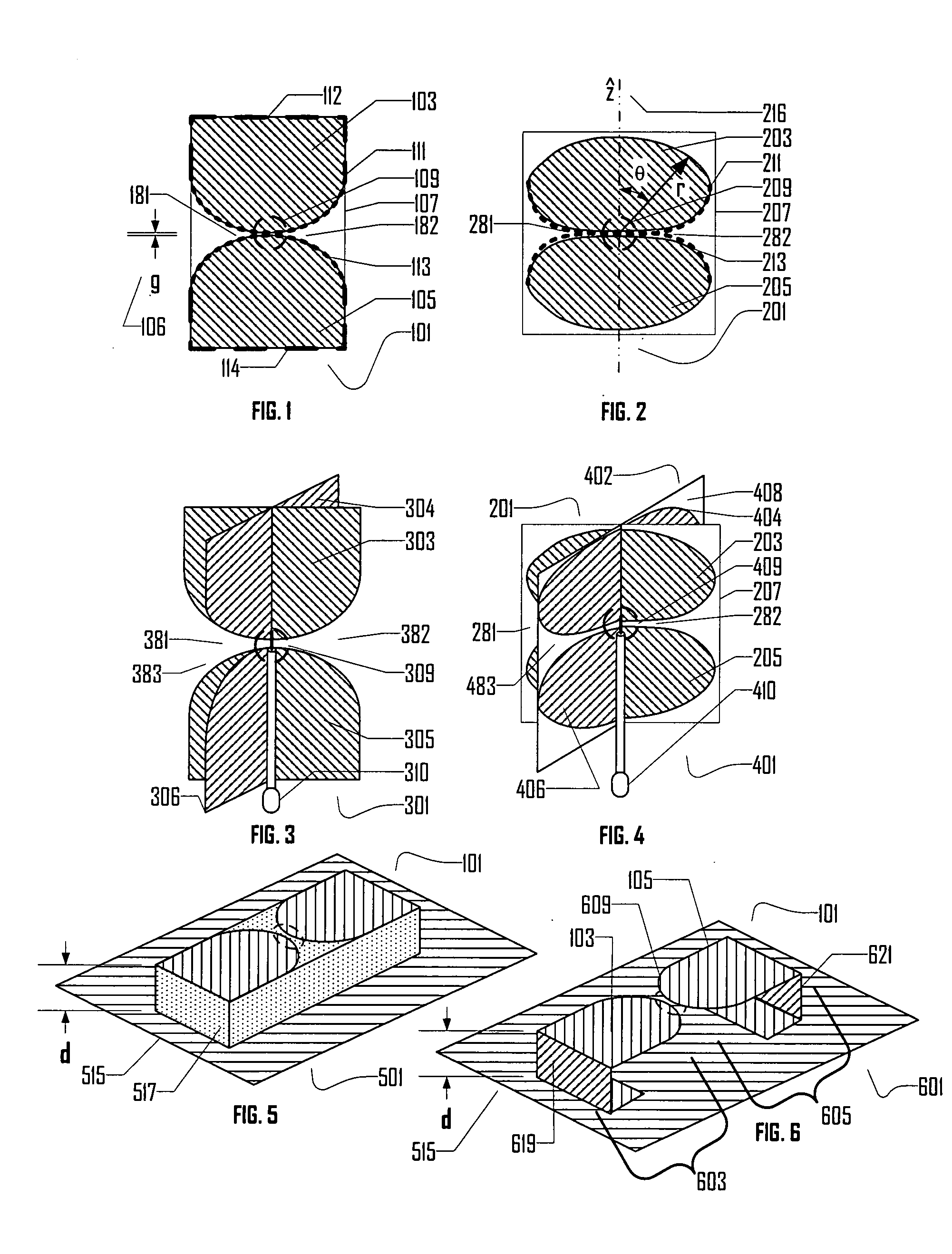
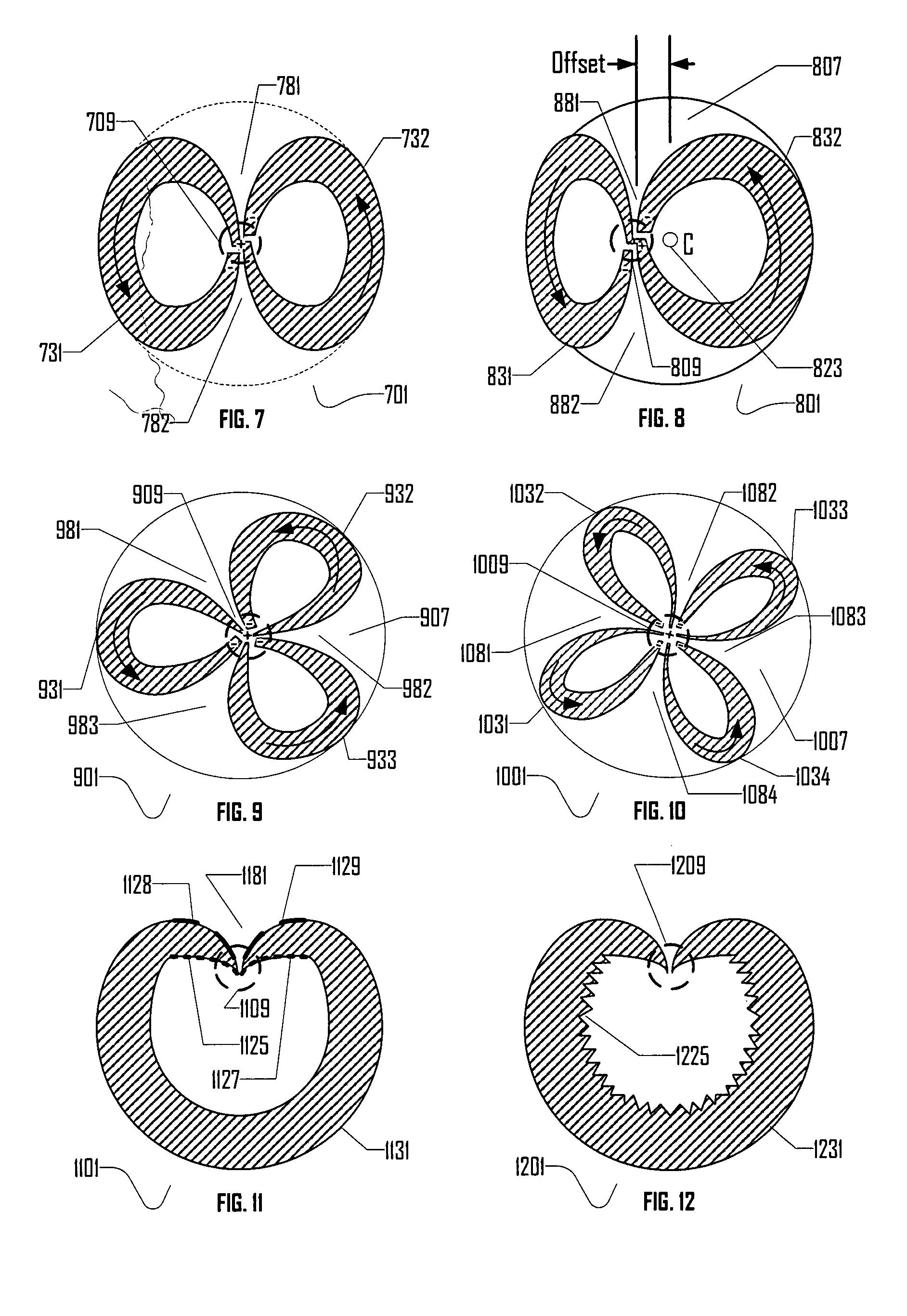
[0094]FIG. 15 is a schematic diagram of a preferred embodiment broadband electric-magnetic antenna apparatus 1501. Preferred embodiment broadband electric-magnetic antenna apparatus 1501 comprises a four notch multiple plate dipole 301 with elliptically tapered semi-circular elements and a four notch planar loop antenna 1001. In preferred embodiment broadband electric-magnetic antenna apparatus 1501, the number of notches in an electric element (like electric element 301) and the number of notches in a magnetic element (like magnetic element 1001) are identical. A feed region (not visible in FIG. 15) of four notch planar loop antenna 1001 may need to be offset slightly according to the teachings of the present invention so as to effect a successful superposition.

[0095] First electric element edge 1541 and second electric element edge 1543 cooperate to form a vertical notch. First magnetic element edge 1542 and second magnetic element edge 1544 cooperate to form ...


PUM


Abstract

The present invention is directed to a broadband electric-magnetic antenna apparatus and method. The present invention teaches a variety of electric antennas suitable for use in the present invention as well as a variety of magnetic antennas suitable for use in the present invention. Combination of a broadband electric antenna element and a broadband magnetic element to create a broadband electric-magnetic antenna system is discussed. This invention further teaches systems for using a broadband electric magnetic antenna system to radiate or receive quadrature signals.

Description

[0001] This application claims benefit of prior filed co-pending Provisional Patent Application Ser. No. 60 / 538,187 filed Jan. 22, 2004.BACKGROUND OF THE INVENTION [0002] 1. Field of the Invention [0003] The present invention relates to antennas and more specifically to an apparatus and system to combine broadband electric and magnetic antennas so as to create a highly efficient electrically small broadband antenna. [0004] 2. Description of the Prior Art [0005] Broadband antenna systems are in great demand for precision tracking, radar, and communications. A commercially successful UWB antenna system must be both small and efficient. Additionally, it is advantageous for a UWB antenna to radiate and receive signals with polarization diversity. [0006] In related art, Chu, Kraus, and Schantz have considered the theoretical advantages of an electric-magnetic antenna system in which fields from an electric element are arranged ninety degrees out of phase with respect to fields from a mag...

Claims


Application Information

Patent Timeline
IPC IPC(8): H01Q13/10H01Q21/06H01Q21/20H01Q21/29
CPCH01Q13/10H01Q21/29H01Q21/205H01Q21/064
Inventor SCHANTZ, HANS GREGORY
Owner SCHANTZ HANS GREGORY
Why Eureka
Try Eureka