Light scanning device

a scanning device and light technology, applied in the field of light scanning devices, can solve the problems of difficult maintenance of the oscillation of the fast scanning mirror, high and variable mechanical damping, and the reaction of the shell or case of such devices, and achieve the effect of reducing any vibration

Inactive Publication Date: 2005-07-28
OPTISCAN +1
View PDF3 Cites 28 Cited by
  • Summary
  • Abstract
  • Description
  • Claims
  • Application Information

AI Technical Summary

Benefits of technology

[0030] adjusting said device so as to reduce any vibration therein.

Problems solved by technology

Thus a considerable amount of reactive motion of the shell or case of such devices can occur.
While operating, contact between the case of such devices and biological tissue can cause a high and variable degree of mechanical damping.
This damping may also make the oscillation of a fast scan mirror difficult to maintain or may cause substantial changes in the amplitude of vibration.
As a separate effect, the coupling of vibrational energy from a fast resonant scan mirror may also cause unwanted vibration of other components in a scanning head.
Such vibration may have deleterious effects.

Method used


Image

  • Light scanning device
  • Light scanning device
  • Light scanning device

Examples


second embodiment

[0066] The scanning element of the second embodiment is also provided with an electrostatic drive, shown schematically in FIG. 4. The electrostatic drive comprises two alternating power supplies 142a and 142b, each connected to electrodes 144a and 144b respectively and attached to the mirror 122 and counterbalancing element 124 in the following manner.

[0067] Electrode 144a extends from power supply 142a, proceeds along torsion bar 126 to counterbalancing element 124, then around counterbalancing element 124 in approximately a semicircle until it again reaches torsion bar 126, follows torsion bar 126 to mirror 122, and passes around the periphery of mirror 122 in approximately a semicircle remote from its path around counterbalancing element 124 until it reaches torsion bar 126. By means of power supply 142a, therefore, the upper (in the view of FIG. 4) portion of counterbalancing element 124 and the lower portion of mirror 122 can be simultaneously charged.

[0068] Electrode 144b of ...

third embodiment

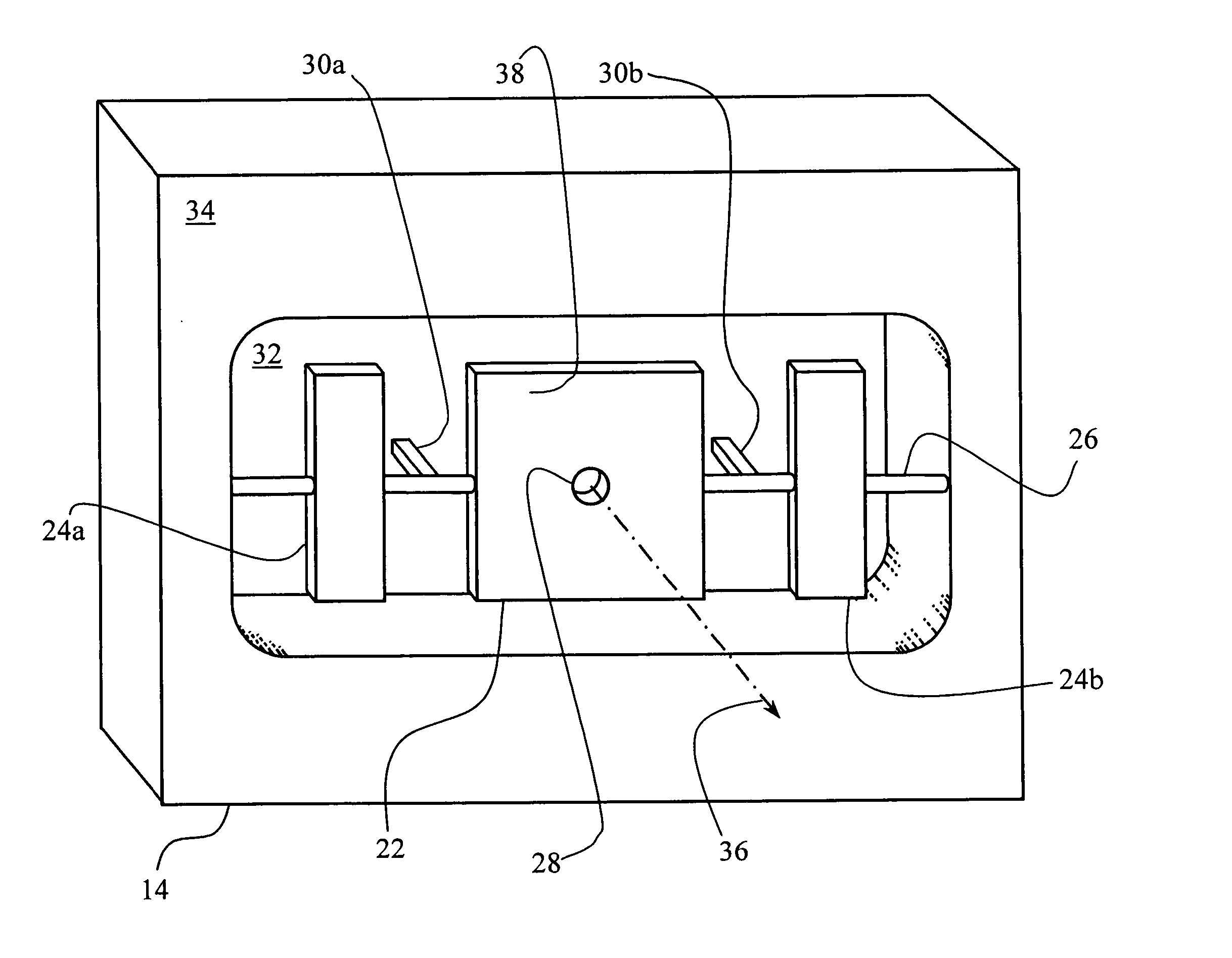
[0072]FIG. 5 is an exploded, schematic view of the scanning element 214 of the present invention. The scanning element 214 includes a forward frame 234, including a mirror 222 pivotably mounted on a torsion bar 226. Mirror 222 includes a circular, central aperture 228. Optical fiber 208 is arranged with its exit tip 230 behind (in the view of FIG. 5) and aligned with central aperture 228.

[0073] Mirror 222 is driven in an oscillatory or swinging manner by means of an electrostatic or electromagnetic drive (see above).

[0074] Scanning element 214 also includes a rear frame 250, mechanically coupled to forward frame 234 by means of four corner pillars 252.

[0075] Rear frame 250 is, in most respects, similar with forward frame 234. However, instead of having a pivotable mirror, rear frame 250 includes a similarly arranged pivotable circular counterbalance mounted on a torsion bar. The scanning element 214 is configured, however, so that the counterbalancing element of rear frame 250 is ...


PUM


Abstract

The invention provides a light scanning device for scanning light from a light source, the light scanning device having: a pivotably mounted mirror for receiving light from the light source; a counterbalance; and a drive for oscillatorily pivoting the mirror and the counterbalance simultaneously in opposite directions to reduce uncoupled forces.

Description

FIELD OF THE INVENTION [0001] The present invention relates to a light scanning device, of particular but by no means exclusive application in the fields of scanning microscopy and scanning endoscopy. [0002] One existing scanning microscope is disclosed in International Patent Application No. WO 99 / 04301. This microscope employs a miniature tuning fork to one tine of which is attached an optical fiber light source. The tuning fork is driven by electromagnets at a frequency of approximately 1000 Hz so that the output of the optical fiber is scanned in the direction of vibration of the tuning fork. [0003] Another technique is disclosed in related U.S. Pat. Nos. 6,172,789 and 6,057,952. The system disclosed in these documents includes a moveable mirror, a fixed mirror and a converging lens. The moveable mirror has an opening at its centre and is supported to be swingable about at least one axis. The fixed mirror is fixedly supported by an optically transparent plate, with its reflectio...

Claims


Application Information

Patent Timeline
Patent Type & Authority Applications(United States)
IPC IPC(8): G02B21/00G02B23/24G02B26/08G02B26/10H04N1/113
CPCG02B21/002G02B23/2407G02B26/105G02B26/0858G02B26/0841
Inventor HARRIS, MARTIN RUSSELL
Owner OPTISCAN
Why Eureka
Try Eureka