Flat type light condensing device

a light condensing device and flat-type technology, applied in the direction of mountings, optics, instruments, etc., can solve the problems of deterioration of the modulation transfer function (mtf), and achieve the effects of reducing the occupied space of the optical path device, facilitating design, and reducing unwanted intermixing of data

Inactive Publication Date: 2005-07-28
TECO IMAGE SYST
View PDF6 Cites 2 Cited by
  • Summary
  • Abstract
  • Description
  • Claims
  • Application Information

AI Technical Summary

Benefits of technology

[0007] The primary object of the present invention is to provide a flat type light condensing device. The present invention mainly provides a flat type light condensing lens used in a scanner to reduce the occupied space in an optical path device and also facilitate the design. Moreover, only data of a single line are captured to reduce unwanted intermixing of data from other lines for enhancing the MTF of the scanner and further letting the brightness be more uniform when imaging.
[0009] Another object of the present invention is to provide an optical path device comprising the above light condensing device. The structure design of the optical path device can be simplified. Moreover, the travel path of light won't be interfered, and the height can be reduced.

Problems solved by technology

In the prior art, data of other lines may easily intermix to result in deterioration of the modulation transfer function (MTF).

Method used


Image

  • Flat type light condensing device
  • Flat type light condensing device
  • Flat type light condensing device

Examples


Embodiment Construction

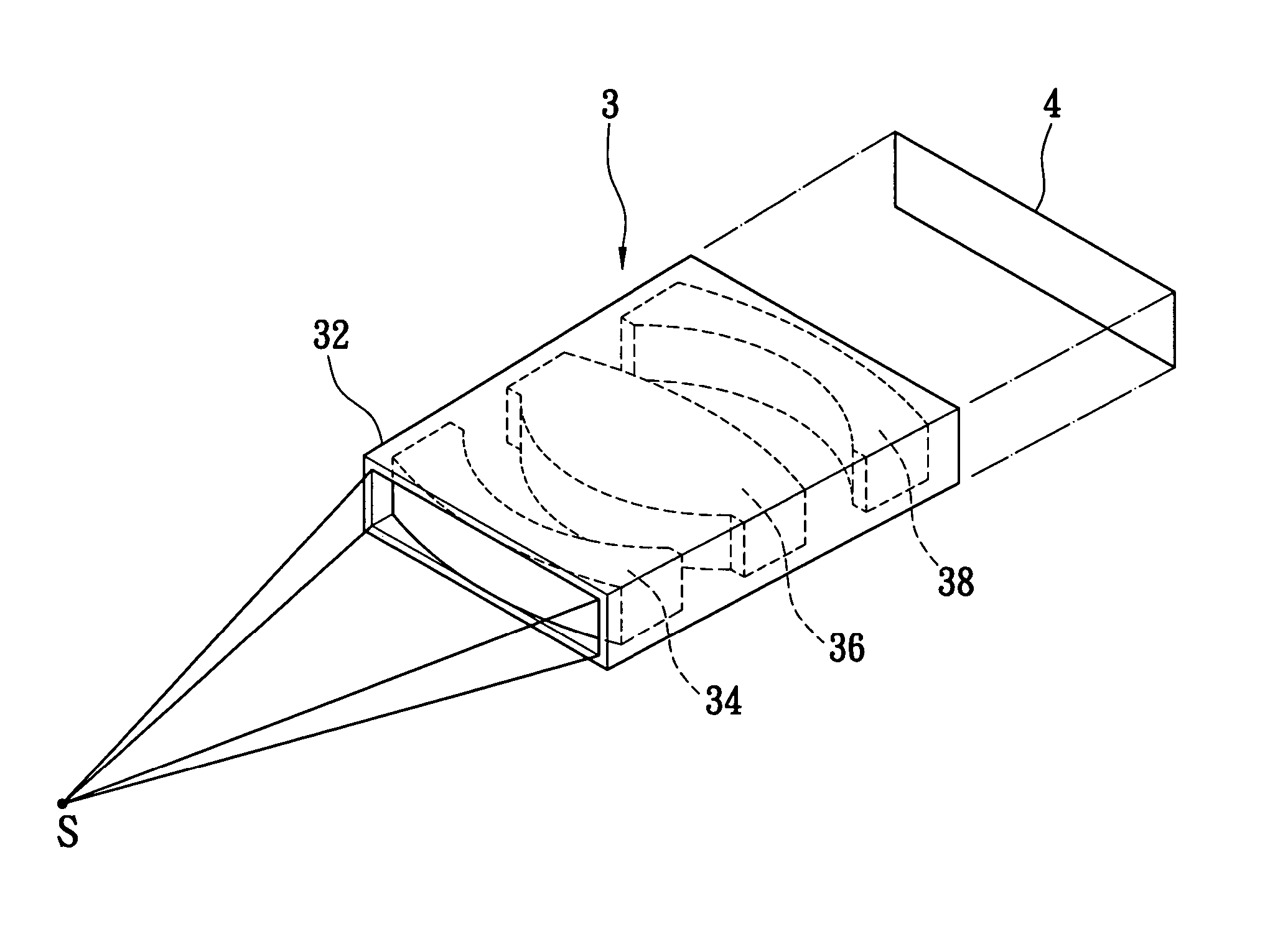
[0023] As shown in FIGS. 5 and 6, a light condensing device 3 is arranged in an optical path device of an optical equipment, e.g., an optical engine of a scanner. The flat type lens 3 has a frame 32 having a rectangular cross section. The frame 32 is a flat type shell having two rectangular openings. A lens set 30 is provided in the frame 32. The lens set 30 comprises a plurality of rectangular lenses 34, 36 and 38 for condensing light to form an image onto an OE converter 4 (e.g., a CCD). The frame 32 is made of plastic, metal or ceramic material. The lenses 34, 36 and 38 can be made by molding of cutting glass, but the cost will be high. In the present invention, it is preferred that the lenses 34, 36 and 38 be made by means of precise plastic injection molding to achieve a lower cost. The precise plastic injection molding is used in lenses of digital still cameras today and won't be further described below.

[0024] The lens set 30 at least comprises a light incidence piece 34, a l...


PUM


Abstract

A flat type light condensing device used in an optical path device includes a hollow frame whose two ends have rectangular openings and a plurality of lenses arranged in the frame. The flat type light condensing lens is used in a scanner to reduce the occupied space in an optical path device and also facilitate the design. Moreover, only data of a single line are captured to reduce unwanted intermixing of data from other lines for enhancing the MTF of the scanner and further letting the brightness be more uniform when imaging.

Description

FIELD OF THE INVENTION [0001] The present invention relates to a flat type light condensing device and, more particularly, to a light condensing lens used in a scanner or a copier to condense light reflected by a manuscript and image onto an optical-to-electric (OE) converter. BACKGROUND OF THE INVENTION [0002] In a common image readout device, an optical path device (usually called an optical engine) reflects light many times. A light condensing device (usually a lens) then focuses light for imaging. Next, an optical-to-electric (OE) converter converts optical signals into electric signals to be processed and memorized by electronic devices. The OE converter commonly used in the industry today is a charge coupled device (CCD), and can also be a complementary metal-oxide semiconductor (CMOS) device. During travel of light, a certain length of optical path is required for imaging to narrow its width. Therefore, several reflecting mirrors are generally used to let the imaging width of...

Claims


Application Information

Patent Timeline
Patent Type & Authority Applications(United States)
IPC IPC(8): G02B7/02G02B19/00G02B27/09H04N1/03
CPCG02B27/0927G02B19/0014G02B19/0047H04N1/03
Inventor LEE, PEN-JUNG
Owner TECO IMAGE SYST
Why Eureka
Try Eureka