
Duplicate data storing system, duplicate data storing method, and duplicate data storing program for storage device

a data storage system and data storage technology, applied in the field of duplicate data storage system, duplicate data storage method, duplicate data storage program, can solve the problem of extremely small storage capacity required for building the data storage area managing device, and achieve the effect of reducing storage capacity, eliminating fragmentation, and effective use of real data storage area storage capacity

Inactive Publication Date: 2005-07-28
NEC CORP
View PDF4 Cites 18 Cited by
  • Summary
  • Abstract
  • Description
  • Claims
  • Application Information

AI Technical Summary

Benefits of technology

[0043] When the data is written to the real data storage area, the data storage area determining device determines the next storage area to be used in a contiguous arrangement for storing the data in order. Therefore, there is no vacant area to be formed carelessly in the real data storage area so that the storage capacity of the real data storage area can be saved and the data reading-out efficiency from the duplicate volume by pre-fetch can be improved.
[0097] Further, when writing the data to the real data storage area, the data storage area determining device determines the next storage area to be used in a contiguous arrangement for storing the data in order. Therefore, there is no vacant area to be formed carelessly in the real data storage area so that the storage capacity of the real data storage area can be saved and the data reading-out efficiency from the duplicate volume by pre-fetch can be improved.

Problems solved by technology

The data storage area managing device is a kind of index table so that the storage capacity required for building the data storage area managing device is extremely small.

Method used


Image

  • Duplicate data storing system, duplicate data storing method, and duplicate data storing program for storage device
  • Duplicate data storing system, duplicate data storing method, and duplicate data storing program for storage device
  • Duplicate data storing system, duplicate data storing method, and duplicate data storing program for storage device

Examples


first embodiment

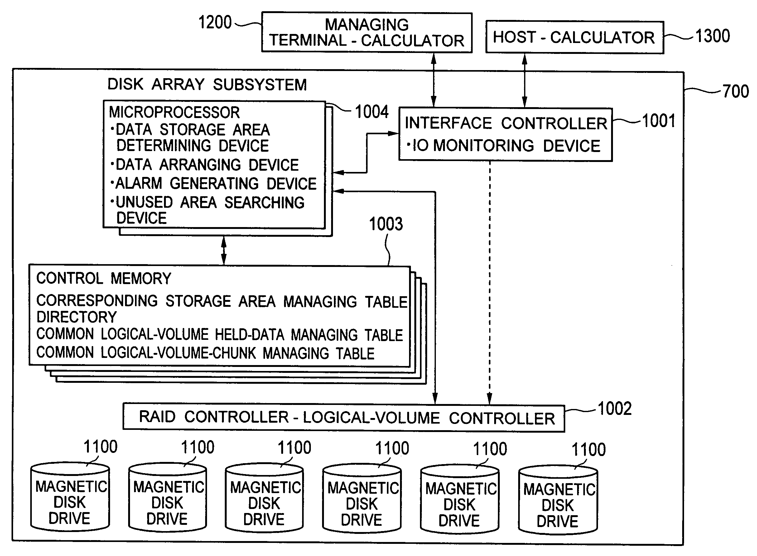
[0142]FIG. 11 is a functional block diagram for simply illustrating a disk array subsystem 700 of a first embodiment from a functional point of view.

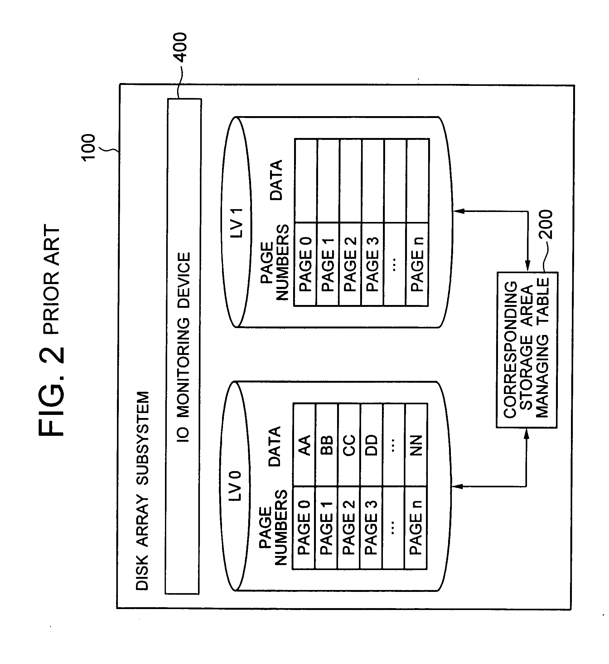
[0143] As shown in FIG. 11, schematically, the disk array subsystem 700 comprises: snapshot-target volumes 701, 703 to which original data is stored, snapshot duplicate volumes 702, 704 functioning as duplicate data storage areas; a corresponding storage area managing table 708 for managing the states of the snapshot-target volumes 701, 703 and the snapshot duplicate volumes 702, 704; a common logical-volume 705 functioning as a real data storage area which is an actual storage area of the duplicate data; an IO monitoring device 707 for controlling each unit by monitoring input / output data to / from the disk array subsystem 700; and an address conversion device 706 for managing mapping of data from the snapshot duplicate volumes 702, 704 to the common logical-volume 705.

[0144] There is no specific limit in the number of the snapshot-tar...

second embodiment

[0212] Next, the memory unit managing device for managing the memory unit set in the common logical-volume will be described by referring to an embodiment in which it is provided to the address conversion device 706.

[0213] As shown in FIG. 24, the address conversion device 706 of the embodiment comprises a directory 801, a common logical-volume held-data managing table 802, a data storage area determining device 803, and a common logical-volume chunk managing table 1703 which functions as a memory unit managing device. The common logical-volume chunk managing table 1703 is enclosed in a control memory 1003.

[0214] Further, as shown in FIG. 25, the IO monitoring device 707 comprises a host-command fetching device 401, an IO size informing device 1802, an initializing device 403 of corresponding storage area managing table, and a host-command dividing device 403.

[0215] Then, as shown in FIG. 26, the data storage area determining device 803 comprises an unused area searching device 9...

third embodiment

[0232] Next, described is an embodiment in which a data arranging device for rearranging the data is provided in each real data storage area.

[0233] As shown in FIG. 29, the address conversion device 706 of the embodiment comprises a directory 801, a common logical-volume held-data managing table 802, a data storage area determining device 803, and a data arranging device 2204.

[0234] In the embodiment, writing to the snapshot duplicate volume is not performed by each memory unit peculiar to the disk array subsystem 700 but is performed by each chunk unit which is kinetically determined according to the IO size designated by the write-command.

[0235] Upon receiving the write-command from the host, the IO monitoring device 707 informs the IO size of the command to the data storage area determining device 803 through the IO size informing device (1802 in FIG. 25). The unused area size determining device (1902 in FIG. 30) determines the chunk size from the informed IO size and the memo...


PUM


Abstract

Provided is a data storing system which holds only updated data by a snapshot action of a disk array subsystem. When there is generated a writing request to snapshot duplicate volumes as the duplicate data storing areas, unused pages for the requested amount is searched from a common logical-volume which is used in common as a real data storage area within the disk array subsystem, and address conversion of the page is performed. The result of the address conversion is held in a directory which is provided for each of the snapshot duplicate volumes. When making an access to the page thereinafter, the directory is always being referred to, and the address conversion is performed from the page of the snapshot duplicate volumes to the corresponding page of the common logical-volume.

Description

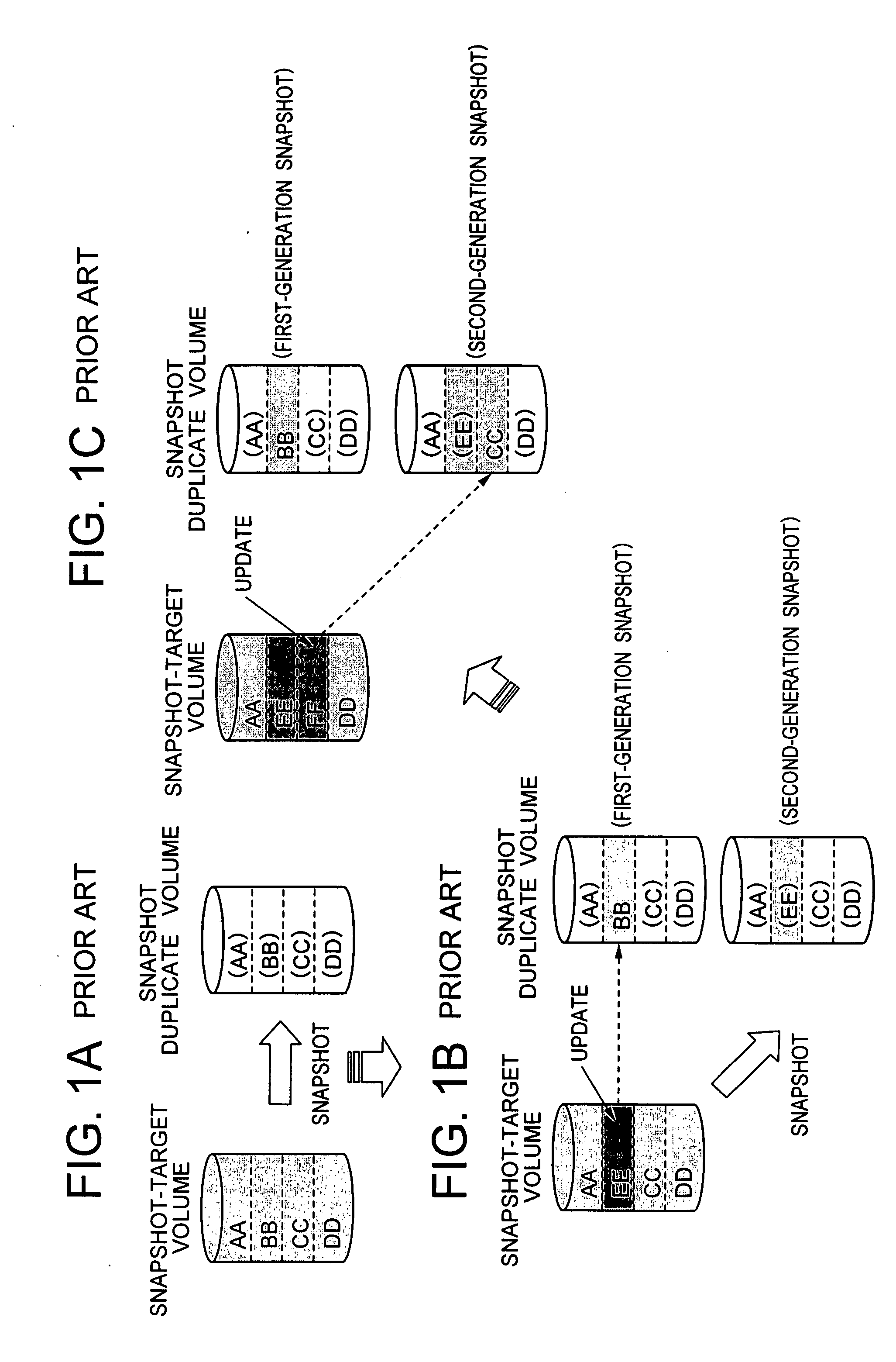
BACKGROUND OF THE INVENTION [0001] 1. Field of the Invention [0002] The present invention relates to storing data into a storage device of a disk array subsystem and the like and, especially, to a duplicate data storing system, a duplicate data storing method, and a duplicate data storing program, which enable to improve an effective usage of the storage device capacity in a duplicate data storage area at the time of using snapshot technique while maintaining the disk-access performance. [0003] 2. Description of the Related Art [0004] When backing up the volume which constitutes a duplicate data storage area in a storage device of a disk array subsystem and the like, the volume as a backup target is duplicated inside the disk array subsystem and a backup server stores data read out from the duplicate data storage area to be the duplicate volume to a backup medium such as a tape drive. [0005] As the method for duplicating the volume, conventionally used is a method in which a complet...

Claims


Application Information

Patent Timeline
IPC IPC(8): G06F12/00G06F11/14G11B7/0045G11B7/28
CPCG06F11/1435G06F2201/84G06F11/1466G11B7/28G11B7/00456
Inventor SOEDA, NAOKI
Owner NEC CORP
Learn More