Patch density measuring apparatus and image forming apparatus

a technology of patch density and measuring apparatus, which is applied in the direction of electrographic process apparatus, photometry using reference value, instruments, etc., can solve the problems of complex configuration of the apparatus and the process of measuring patch density, so as to avoid improper density correction and avoid image quality degradation

Active Publication Date: 2005-07-28
BROTHER KOGYO KK
View PDF7 Cites 24 Cited by
  • Summary
  • Abstract
  • Description
  • Claims
  • Application Information

AI Technical Summary

Benefits of technology

[0027] Therefore, in the image forming apparatus as above, it can avoid the quality of the image from being deteriorated by avoiding the improper density correction.

Problems solved by technology

Consequently, the process for measuring the patch density as well as the configuration of the apparatus becomes complicated.

Method used


Image

  • Patch density measuring apparatus and image forming apparatus
  • Patch density measuring apparatus and image forming apparatus
  • Patch density measuring apparatus and image forming apparatus

Examples


Embodiment Construction

[0041] Although the present invention has been described in connection with the above embodiment, the present invention is not limited to the embodiment but may have a various forms.

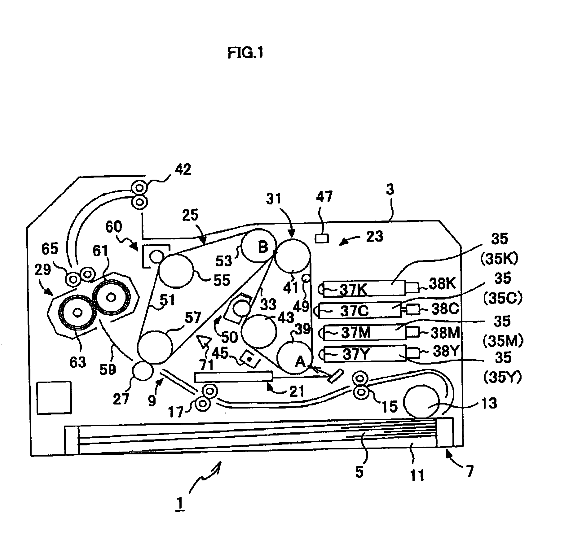
[0042] Referring to FIG. 1, the color laser printer 1 takes 4 cycle system. Within a casing main body 3, there are provided a sheet supply unit 7 for supplying a sheet 5, and an image forming unit 9 for forming a certain image on the supplied sheet 5.

[0043] The sheet supply unit 7 comprises a sheet supply tray 11, in which the sheet 5 is accommodated in the form of stacked paper, a sheet supply roller 13 which abuts on the sheet 5 positioned on the top of the paper supply tray 11 and picks up one sheet 5 at a time by rotation, conveying rollers 15 which conveys the sheet 5 to an image forming position, and registration rollers 17.

[0044] The image forming position indicates a transfer position where a toner image on an inter transfer belt 51 (described hereinafter) is transferred on the sheet 5. In the...


PUM

PropertyMeasurementUnit
collecting bias voltageaaaaaaaaaa
electric potentialaaaaaaaaaa

Abstract

When a regular reflection light receiving unit is receiving a reflected light in a non-image area where the test patches are not formed, a clamp switch is closed. Then, a first reference voltage generated by a pull-up resistor and a zener diode is corresponded to an electric potential of a terminal of a capacitor on the side of an A/D converter. The capacitor is charged by the difference in electric potential between the first reference voltage and an output voltage from the regular reflection light receiving unit. Next, the clamp switch is opened. After the regular reflection light receiving unit receives the reflected light from an image area where the test patches are formed with this state of things, the output voltage from the regular reflection light receiving unit is changed. The difference in density between the image area and the non-image area can be quantified by the A/D converter.

Description

BACKGROUND OF THE INVENTION [0001] (1) Field of the Invention [0002] The present invention relates to a patch density measuring apparatus which measures the density of patches formed on a transfer medium and an image forming apparatus which has such a patch density measuring apparatus. [0003] (2) Background Art [0004] In order to avoid the density of an image formed by toner from being changed due to a secular change in apparatus and an environmental change, there has been conventionally known an electrostatographic image forming apparatus which has functions to form patches (test pattern), measure the patch density, and correct the density of the image based on the measurement result (for example, see Publication of Japanese Patent No. 3272768). [0005] In a density measuring apparatus provided to the image forming apparatus, when the patch density is measured, the density corresponding to the dirt or scratch of the surface of a transfer medium (base) is measured by a sensor. The se...

Claims


Application Information

Patent Timeline
Patent Type & Authority Applications(United States)
IPC IPC(8): G01J1/18G01N21/47G01N21/55G03G15/00G03G21/00
CPCG03G2215/0164G03G15/5058G03G15/5041
Inventor TAKAHASHI, OSAMU
Owner BROTHER KOGYO KK
Why Eureka
Try Eureka