Direct writeTM system

a writetm system and material technology, applied in the direction of superimposed coating process, liquid/solution decomposition chemical coating, manufacturing tools, etc., can solve the problem of limiting the variety of materials which may be deposited, so as to achieve the effect of enhancing deposition

Inactive Publication Date: 2005-07-28
OPTOMEC DESIGN CO
View PDF99 Cites 76 Cited by
  • Summary
  • Abstract
  • Description
  • Claims
  • Application Information

AI Technical Summary

Problems solved by technology

Although inkjet printing offers a relatively versatile and inexpensive process for applying a material to a substrate, ink jet printing is generally limited to placing exceedingly thin layers of ink on paper or cloth which are essentially two-dimensional.
This limited range of viscosity in turn limits the variety of materials which may be deposited.
As a result, mechanical connections may not be made to layer built using a photolithographic layer.
The limitations to Fodel® are: 1) The Fodel® process is purely planar.
No three-dimensional features can be produced.
4) The material costs of the Fodel® process are relatively high.
5) The Fodel® process is limited to features larger than 50 microns.

Method used


Image

  • Direct writeTM system
  • Direct writeTM system
  • Direct writeTM system

Examples


Embodiment Construction

I. Direct Write™ Methods & Apparatus

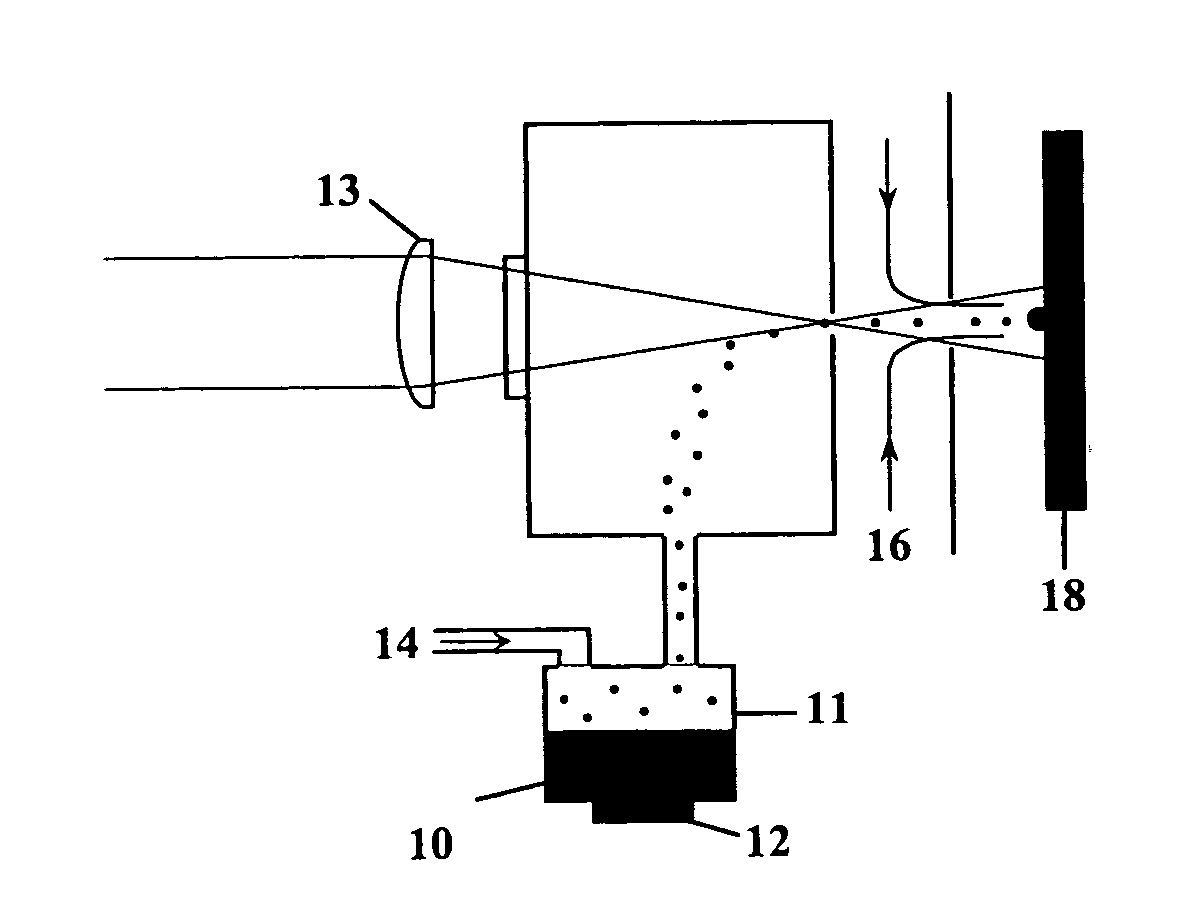
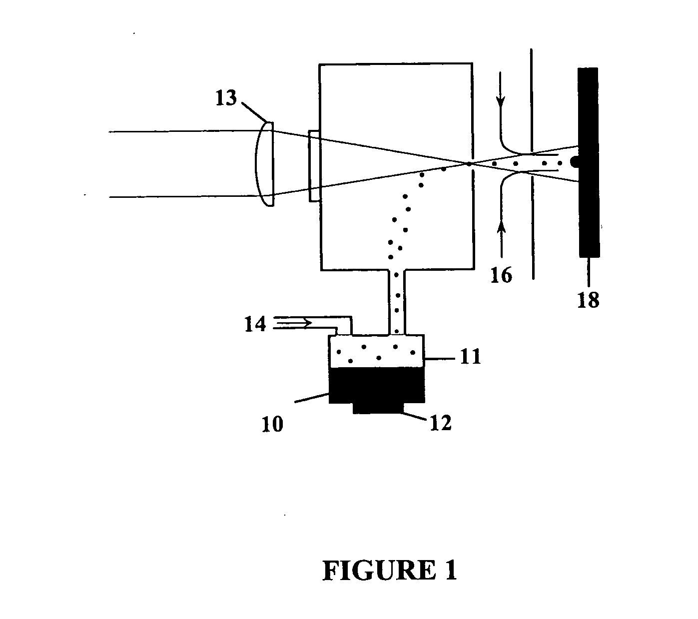
[0045]FIG. 1 presents a a schematic view of one of the preferred embodiments of the Direct Write™ System, which comprises methods and apparatus for maskless, mesoscale deposition of a source material on a substrate. Unlike many previous deposition systems which are restricted to the formation of planar layers on a flat substrate, the present invention is capable of forming a wide variety of planar, non-planar, conformal or three-dimensional features on a substrate having virtually any profile or topography.

[0046] In one embodiment, the invention comprises a source of material 10 contained by an enclosure 11. Although the a preferred embodiment generally includes a source material in liquid form, the source may comprise any aggregation, mixture, suspension or other combination of any materials in any physical phase. The source of material 10 is contained in a vessel, pool, volume or chamber which is coupled to or in communication with an atomizer ...


PUM

PropertyMeasurementUnit
viscosityaaaaaaaaaa
viscosityaaaaaaaaaa
feature sizeaaaaaaaaaa

Abstract

Although the present invention has been described in detail with reference to particular preferred and alternative embodiments, persons possessing ordinary skill in the art to which this invention pertains will appreciate that various modifications and enhancements may be made without departing from the spirit and scope of the Claims that follow. The various configurations that have been disclosed above are intended to educate the reader about preferred and alternative embodiments, and are not intended to constrain the limits of the invention or the scope of the Claims. The List of Reference Characters which follows is intended to provide the reader with a convenient means of identifying elements of the invention in the Specification and Drawings. This list is not intended to delineate or narrow the scope of the Claims.

Description

CROSS-REFERENCE TO RELATED APPLICATIONS [0001] This application is a continuation application of U.S. patent application Ser. No. 10 / 072,605, entitled “Direct Write™ System”, to Michael J. Renn, filed on Feb. 5, 2002 and the specification thereof is incorporated herein by reference. [0002] This application also claims the benefit of the filing of U.S. Provisional Patent Application Ser. No. 60 / 102,418, entitled “Laser-Guided manipulation of Non-Atomic Particles” filed on Sep. 30, 1998; PCT Patent Application No. PCT / US99 / 22527, entitled “Laser-Guided manipulation of Non-Atomic Particles,” filed on Sep. 30, 1999; U.S. patent application Ser. No. 09 / 408,621, entitled “Laser-Guided manipulation of Non-Atomic Particles,” filed on Sep. 30, 1999; U.S. patent application Ser. No. 09 / 584,997, entitled “Particle Guidance System,” filed Jun. 1, 2000; PCT Application No. PCT / US01 / 14841, entitled “Particle Guidance System,” filed May 30, 2001; and U.S. patent application Ser. No. 10 / 060,960, en...

Claims


Application Information

Patent Timeline
Patent Type & Authority Applications(United States)
IPC IPC(8): B05D5/12B41J2/015B41J2/02B41J29/38C23C4/12C23C18/00C23C24/04H01L21/60H05K3/10
CPCC23C24/04B41J2/435H01L24/81H01L2224/13099H01L2224/24011H01L2224/76155H01L2224/81801H01L2224/82H01L2224/85H01L2224/86H01L2924/01002H01L2924/01013H01L2924/01015H01L2924/01018H01L2924/01022H01L2924/01025H01L2924/01027H01L2924/0103H01L2924/01046H01L2924/01047H01L2924/01056H01L2924/01074H01L2924/09701H01L2924/14H01L2924/19041H01L2924/19042H01L2924/19043H01L2924/30107H01L2924/3025H05K3/102H01L2924/01005H01L2924/01006H01L2924/01023H01L2924/01033H01L2924/01087B41J2/215H01L24/11H01L2924/12042B41J2/415H01L2924/00C23C4/12
Inventor RENN, MICHAEL J.
Owner OPTOMEC DESIGN CO
Why Eureka
Try Eureka