
Endoscope apparatus

a technology of endoscope and assisting tool, which is applied in the field of endoscope equipment, can solve the problems of difficult extraction of the endoscope insertion section from the insertion assisting tool, and achieve the effects of easy extraction, easy augmentation, and easy augmentation in diameter

Active Publication Date: 2005-07-28
SRJ +1
View PDF19 Cites 92 Cited by
  • Summary
  • Abstract
  • Description
  • Claims
  • Application Information

AI Technical Summary

Benefits of technology

[0010] According to the first aspect of the present invention, the tip end part of the insertion assisting tool is constructed to have the diameter enlarging structure, and therefore, the insertion section having the balloon which is protruded from the tip end of the insertion assisting tool can be easily extracted from the insertion assisting tool.
[0011] According to a second aspect of the present invention, the diameter enlarging structure is characterized by being made capable of being enlarged in diameter by constructing the tip end part of the insertion assisting tool by a soft member. Namely, a soft member such as rubber, sponge or the like is used for the material of only the throttled portion of the tip end part of the insertion assisting tool, whereby the tip end part is easily enlarged in diameter, and therefore, the insertion section having the balloon protruded from the tip end of the insertion assisting tool can be easily extracted from the insertion assisting tool.
[0012] According to a third aspect of the present invention, in order to attain the aforementioned object, the diameter enlarging structure is characterized by being made capable of being enlarged in diameter by forming a notch in the tip end part of the insertion assisting tool. By enhancing flexibility by forming a notch in the throttled portion of the tip end part of the insertion assisting tool, the tip end part is easily enlarged in diameter, and therefore, the balloon can be easily extracted.
[0013] A fourth aspect of the present invention is in an endoscope apparatus comprising an endoscope with a balloon attached to a tip end part of an insertion section by a catching member, and an insertion assisting tool into which the insertion section of the endoscope is inserted and which assists the insertion section in being inserted into a body cavity, characterized in that a surface of the catching member is formed into an inclined surface toward a downstream side from an upstream side in an extracting direction of the insertion section with respect to the insertion assisting tool, and thereby, the balloon of the insertion section protruded from the tip end of the insertion assisting tool is made extractable from the insertion assisting tool. The surface of the catching member is formed into the inclined surface of which height becomes larger toward the downstream side from the upstream side in the extracting direction, and the balloon is made extractable from the insertion assisting tool. Namely, when the insertion section is pulled in the extracting direction, the tip end of the insertion assisting tool rides on the inclined surface of the catching member and the balloon sinks inside the tip end part, and therefore, the insertion section can be easily extracted from the insertion assisting tool.
[0014] In order to attain the aforesaid object, a fifth aspect of the present invention is in an endoscope apparatus comprising an endoscope with a balloon attached to a tip end part of an insertion section by a catching member, and an insertion assisting tool into which the insertion section of the endoscope is inserted and which assists the insertion section in being inserted into a body cavity, characterized in that the catching member and an outer peripheral surface of the insertion section are made substantially flush with each other by fitting the catching member in a recessed part formed in the outer peripheral surface of the insertion section, and thereby, the balloon of the insertion section protruded from the tip end of the insertion assisting tool is made extractable from the insertion assisting tool. When the insertion section is pulled in the extracting direction, the tip end part of the insertion assisting tool does not collide against the catching member which interferes with the extraction, and therefore, the insertion section can be easily extracted from the insertion assisting tool. By forming the recessed part in the outer peripheral surface of the insertion section to which the catching member is fitted, the outer diameter of the insertion section does not become thick after fitting of the catching member, and the recessed part also serves as the mark of the balloon attaching position.
[0015] According to the present invention, the tip end part of the insertion assisting tool is constructed to have the diameter enlarging structure, and therefore, the balloon of the insertion section protruded from the tip end of the insertion assisting tool can be easily extracted from the insertion assisting tool.

Problems solved by technology

However, the tip end part of the insertion assisting tool has a tip end formed into a throttled shape to prevent an intestinal wall from being entangled or pinched as disclosed in Japanese Patent Application Laid Open No. 2001-340462, and therefore, the balloon of the endoscope insertion section is caught by the tip end part of the insertion assisting tool when the endoscope insertion section is extracted, and it is difficult to extract the endoscope insertion section from the insertion assisting tool.

Method used


Image

  • Endoscope apparatus
  • Endoscope apparatus
  • Endoscope apparatus

Examples


Embodiment Construction

[0030] Hereinafter, preferred embodiments of an endoscope apparatus according to the present invention will be explained in accordance with the attached drawings.

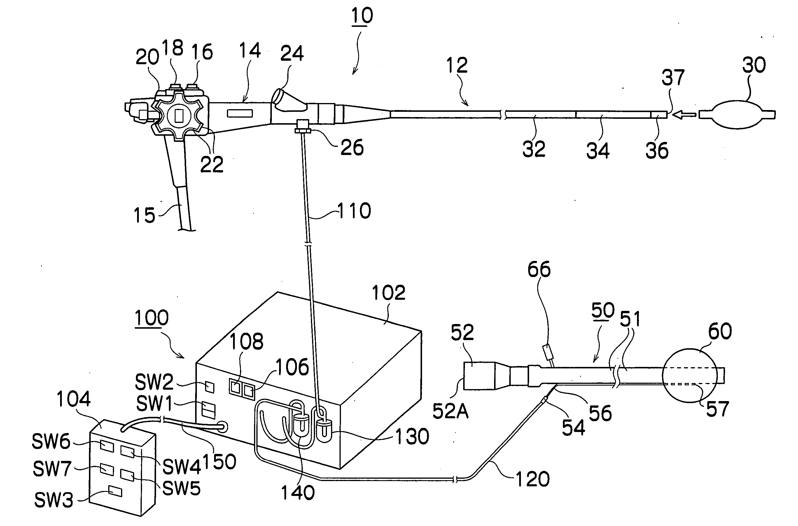
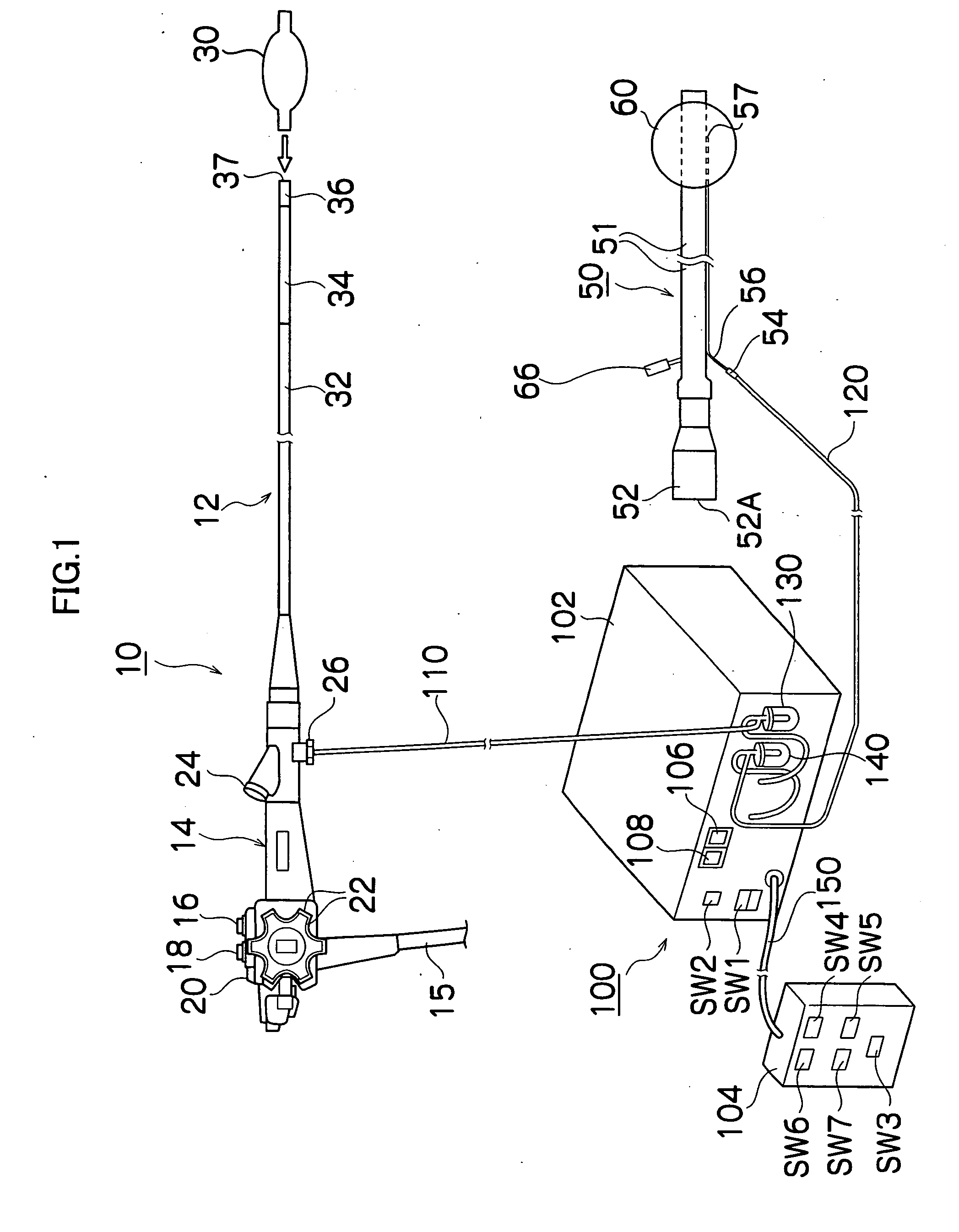
[0031]FIG. 1 shows a system block diagram of an endoscope apparatus according to the embodiments of the present invention. The endoscope apparatus shown in the drawing is constructed by an endoscope 10, an over tube (corresponding to an insertion assisting tool) 50, and a balloon control device 100.

[0032] The endoscope 10 includes a hand operation section 14, and an insertion section 12 connected to the hand operation section 14. A universal cable 15 is connected to the hand operation section 14, and a connecter (not shown) which is connected to a processor and a light source device not shown is provided at a tip end of the universal cable 15.

[0033] An air / water passing button 16, a suction button 18, and a shutter button 20 which are operated by an operator are provided in parallel on the hand operation section 14, and ...


PUM


Abstract

An endoscope apparatus, comprising: an endoscope with a balloon attached to a tip end part of an insertion section, and an insertion assisting tool into which the insertion section of the endoscope is inserted and which assists the insertion section in being inserted into a body cavity, wherein a tip end part of the insertion assisting tool is constructed to have a diameter enlarging structure capable of being enlarged in diameter, and by enlarging a diameter of the tip end part, a balloon of the insertion section protruded from a tip end of the insertion assisting tool is made extractable from the insertion assisting tool.

Description

BACKGROUND OF THE INVENTION [0001] 1. Field of the Invention [0002] The present invention relates to an endoscope apparatus, and more particularly, to an endoscope apparatus having an endoscope with a balloon attached to a tip end of an insertion section, and an insertion assisting tool for guiding the insertion section of the endoscope into a body cavity. [0003] 2. Description of the Related Art [0004] When the insertion section of an endoscope is inserted into a deep alimentary canal such as a small intestine, by only pushing the insertion section into the deep alimentary canal, the force is difficult to transmit to a tip end of the insertion section due to complicated bending of an intestinal canal, and insertion into a deep part is difficult. Thus, there is proposed an endoscope apparatus which prevents excessive bending and deflection of the insertion section by inserting the insertion section into a body cavity with an insertion assisting tool called an over tube or a sliding ...

Claims


Application Information

Patent Timeline
IPC IPC(8): A61B1/00A61B1/005A61B1/01A61B1/31A61B17/22
CPCA61B1/00082A61B1/00154A61B2017/22054A61B1/01A61B1/31A61B1/005
Inventor TAKANO, MASAYUKI
Owner SRJ
Learn More