
Surgical anchor and system

Inactive Publication Date: 2005-07-28
BOARD OF RGT THE UNIV OF TEXAS SYST
View PDF18 Cites 158 Cited by
  • Summary
  • Abstract
  • Description
  • Claims
  • Application Information

AI Technical Summary

Benefits of technology

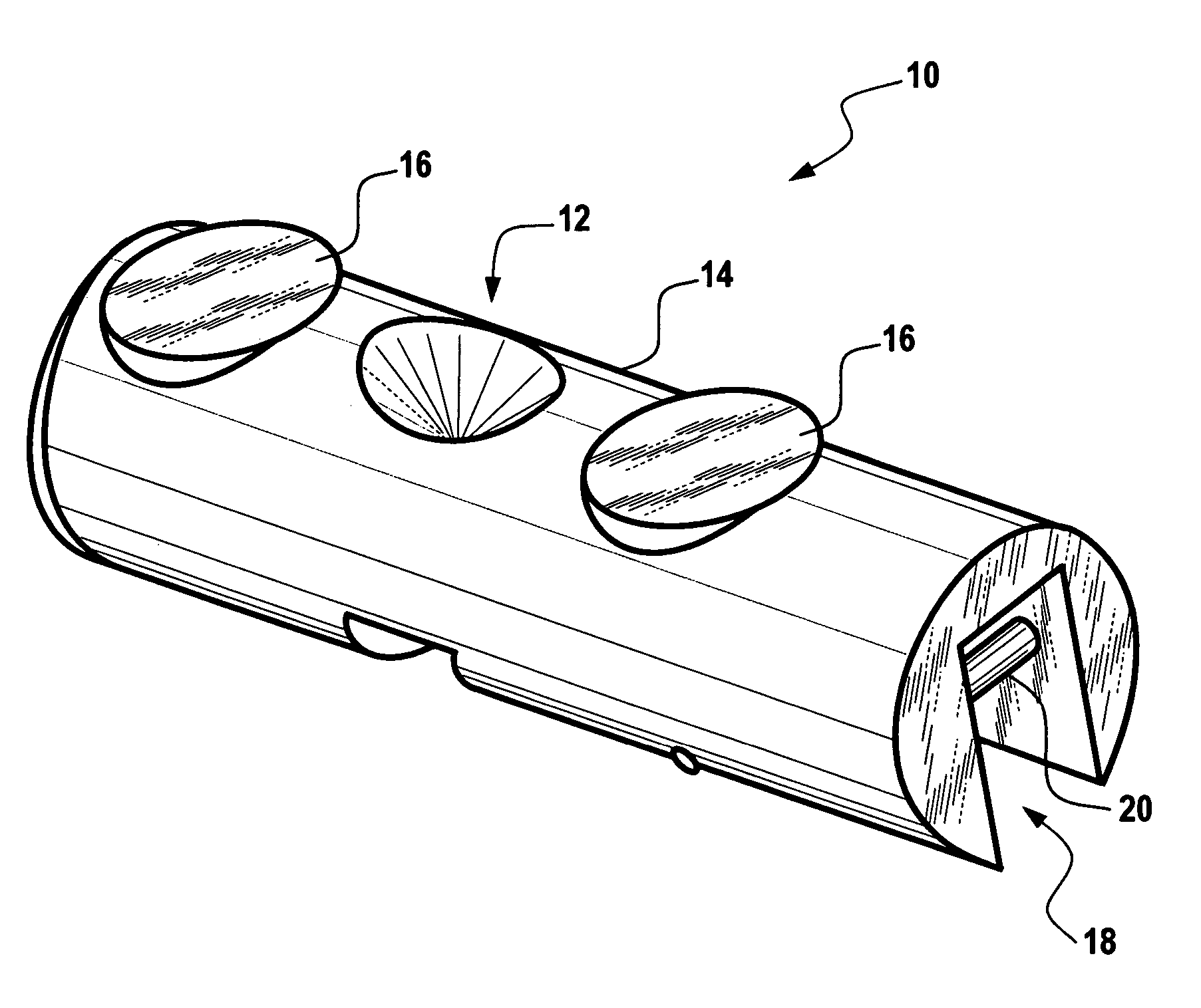
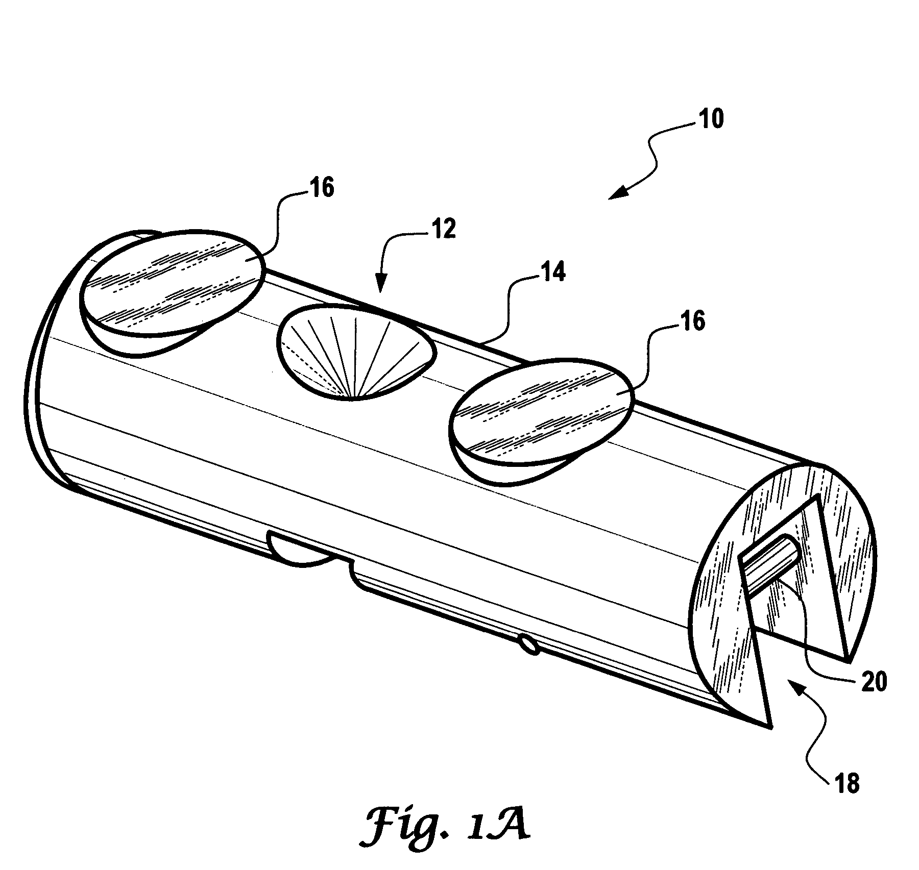
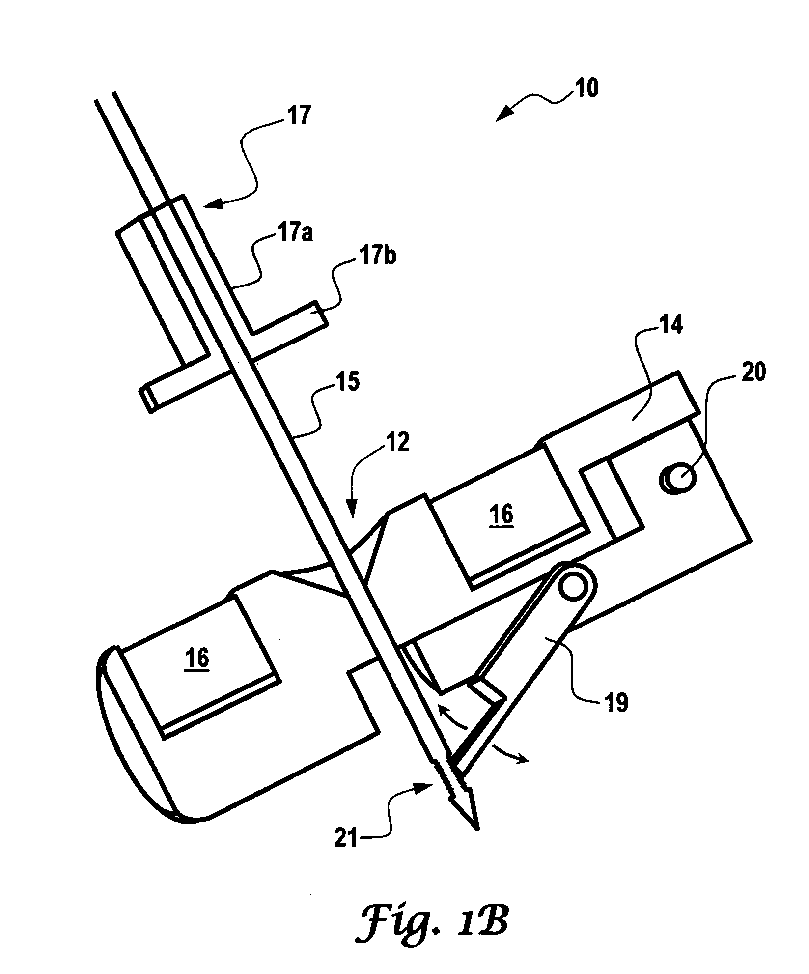
[0005] In order to provide for greater flexibility of endoscopic viewing and instrument usage and to further reduce morbidity, a laparoscopic surgical anchor system has been developed around an internal platform capable of supporting various laparoscopic tools that is secured via a pin or needle to the abdominal wall. The pin is able to provide electrical, mechanical, pneumatic and other power or support externally to the surgical anchor located internally.
[0012] Accordingly, the present inventors have recognized that the field of laparoscopic surgery needs a method and apparatus that enables a surgeon to manipulate the position and orientation of one or more instruments within a human body without the necessity for multiple trocars. To provide for greater flexibility of endoscopic viewing and instrument usage and to further reduce morbidity, the inventors have developed a novel laparoscopic system that allows for unrestricted intra-abdominal movement of an endoscopic camera and surgical instruments without additional port sites.

Problems solved by technology

However, eye-hand dissociation, a two-dimensional field-of-view and fixed instrumentation with limited degrees of freedom contribute to a steep learning curve and demanding dexterity requirements for many laparoscopic procedures.
One of the main limitations of laparoscopy is the fixed working envelope surrounding each trocar, often necessitating placement of multiple ports to accommodate changes in position of the instruments or laparoscope to improve visibility and efficiency.
The placement of additional working ports contributes to post-operative pain and carries a small risk of bleeding or adjacent organ damage.
Problem associated with the invention are that the tool has a limited area of use, the tool is limited by the strength and length of the needle and the tool is limited to the site of insertion.
The limited two and three dimensional field of view within the body cavity may cause insertion of the needle at the wrong location, requiring additional insertions of the shank, thereby increasing greatly the number of skin punctures and increased morbidity from multiple punctures.

Method used


Image

  • Surgical anchor and system
  • Surgical anchor and system
  • Surgical anchor and system

Examples


Embodiment Construction

[0023] The novel features of the present invention will become apparent to those of skill in the art upon examination of the following detailed description of the invention. It should be understood, however, that the detailed description of the invention and the specific examples presented, while indicating certain embodiments of the present invention, are provided for illustration purposes only because various changes and modifications within the spirit and scope of the invention will become apparent to those of skill in the art from the detailed description of the invention and claims that follow.

[0024] The description of laproscopic surgery is set forth to demonstrate the use of the present invention in one type of surgery and is not intended to be exhaustive or to limit the scope of the invention. Many modifications and variations are possible in light of the teachings described herein without departing from the spirit and scope of the following claims. It is contemplated that ...


PUM


Abstract

The present invention is a device and system for manipulating a surgical tool at an intended location, e.g., a confined or inaccessible space, which includes a surgical anchor having at least one opening, wherein the opening provides a catch for a pin; and at least one anchor point to position and orient a surgical tool inside a human body. The apparatus and system of the present invention allows for the use of multiple intra-abdominal surgical tools inserted through a single incision.

Description

TECHNICAL FIELD OF THE INVENTION [0001] The present invention relates to an apparatus and system for performing surgery, and in particular, to a surgical anchor for hands-free operation and control of medical instruments inside a body cavity. BACKGROUND OF THE INVENTION [0002] This application claims priority to U.S. Provisional Application Ser. No. 60 / 526,700, filed Dec. 2, 2003; and U.S. Provisional Application Ser. No. 60 / 536,765, filed Jan. 15, 2004. Without limiting the scope of the invention, its background is described with respect to surgical procedures, and in particular, laparoscopy. [0003] Compared with open surgery, laparoscopy results in significantly less pain, faster convalescence and less morbidity. However, eye-hand dissociation, a two-dimensional field-of-view and fixed instrumentation with limited degrees of freedom contribute to a steep learning curve and demanding dexterity requirements for many laparoscopic procedures. One of the main limitations of laparoscopy...

Claims


Application Information

Patent Timeline
IPC IPC(8): A61B17/04A61B19/00
CPCA61B2017/0472A61B17/0469A61B19/201A61B19/5212A61B2017/00876A61B2017/00283A61B90/11A61B90/361
Inventor CADEDDU, JEFFREY A.BERGS, RICHARD A.FERNANDEZ, RAULBAKER, LINDA
Owner BOARD OF RGT THE UNIV OF TEXAS SYST
Learn More