CPU usage time counting method and job control system using this CPU usage time

a technology of cpu usage and counting method, applied in the direction of program control, instruments, multi-programming arrangements, etc., can solve the problems of constant cpu usage time and incorrect charging of cpu usage time, and achieve the effect of predicting the performance of a cpu and stable servi

Inactive Publication Date: 2005-07-28
FUJITSU LTD
View PDF10 Cites 37 Cited by
  • Summary
  • Abstract
  • Description
  • Claims
  • Application Information

AI Technical Summary

Benefits of technology

[0026] According to the CPU usage time counting method of the present invention and the job control system using this CPU usage time, it is possible to compute the actual CPU usage time and thereby find the same corrected CPU usage time every time by pr

Problems solved by technology

However, the CPU usage time becoming constant every time is true only in an ideal computer.
When predicting the ending time of a certain job or when predicting the performance of a CPU in an en

Method used


Image

  • CPU usage time counting method and job control system using this CPU usage time
  • CPU usage time counting method and job control system using this CPU usage time
  • CPU usage time counting method and job control system using this CPU usage time

Examples


first embodiment

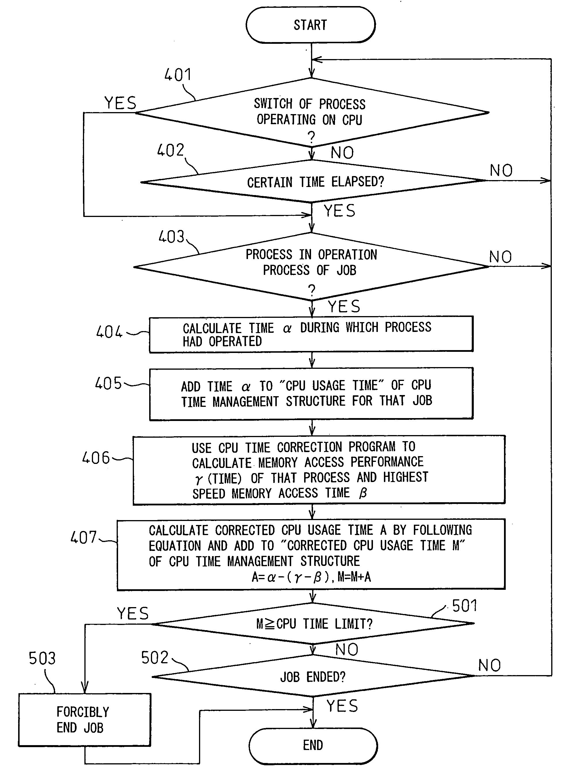
[0056] Here, the CPU usage time count operation for calculating this corrected CPU usage time according to the job management mechanism 20 shown in FIG. 3A will be explained by using the flowchart shown in FIG. 4. This CPU usage time count operation is started up at the time of execution of a job.

[0057] At step 401, it is judged whether or not a process operating on the CPU had been switched. The “process” is the minimum unit of execution of a job. When a switch occurred, the routine proceeds to step 403, while when no switch occurred, the routine proceeds to step 402, where it is judged whether or not a constant time has elapsed after shifting to this process. When the constant time has elapsed, the routine proceeds to step 403, while when the constant time has not elapsed, the routine returns to step 401. The case where it is judged at step 401 that the constant time has elapsed is the case where the job exceeds the limit before the switching of the process.

[0058] When the routin...

second embodiment

[0063]FIG. 5 is a flowchart of the CPU usage time count operation for calculating this corrected CPU usage time according to the job management mechanism 20 shown in FIG. 3A. This is a modification of the CPU usage time count operation explained in FIG. 4. The difference of the CPU usage time count operation shown in FIG. 5 from the CPU usage time count operation explained in FIG. 4 resides in only the processing after step 407. Accordingly, the explanation of the processing from step 401 to step 407 will be omitted, and only portions different from the flowchart explained in FIG. 4 will be explained.

[0064] As explained above, in the first embodiment, at step 407, the corrected CPU usage time A was calculated by A=α−(γ−β), and this calculated time A was added to the time M (described as the “corrected CPU usage time” in FIG. 4) stored in the corrected CPU usage time storage area 24 of the CPU time management structure 23 (M=M+A). In the second embodiment, at the next step 501, it is...

third embodiment

[0067]FIG. 6 is a flowchart of the CPU usage time count operation for calculating this corrected CPU usage time according to the job management mechanism 20 shown in FIG. 3A. This is a modification of the CPU usage time count operation explained in FIG. 5. The difference of the CPU usage time count operation shown in FIG. 6 from the CPU usage time count operation explained in FIG. 5 resides in only the processing after step 407. Accordingly, the processing from step 401 to step 407 are combined as step 600, the explanation thereof is omitted, and only the portions different from the flowchart explained in FIG. 5 will be explained.

[0068] The third embodiment shows the operation when there is a request for notification of the intermediate result of the corrected CPU usage time from a job in the count operation of the corrected CPU usage time or a request for notification of the corrected CPU usage time in the previous job. In the third embodiment, during the count operation of this co...


PUM


Abstract

A method of counting an actual usage time of each CPU in a computer system using a plurality of computers for distributed processing of jobs comprising first counting a CPU usage time used for each job, then counting a processing wait time in memory access of each CPU whenever executing each job, subtracting the processing wait time of each CPU from the CPU usage time for every job, and setting the thus calculated corrected CPU usage time as the actual CPU usage time. A job control system has a means for realizing this method and uses the CPU usage time and the corrected CPU usage time obtained by this means to control the jobs and charge the users.

Description

CROSS-REFERENCE TO RELATED APPLICATIONS [0001] This application is a continuation application of PCT / JP03 / 04087, filed on Mar. 31, 2003, the contents being incorporated herein by reference.TECHNICAL FIELD [0002] The present invention relates to a CPU usage time counting method and a job control system using this CPU usage time, more particularly relates to a method for counting an actual usage time of each CPU when having large scale application processing carried out distributed among a large number of processors (CPUs) and a job control system using this CPU usage time. BACKGROUND ART [0003] In general, in a large scale application using a computer or a processor and used for numerical fluid mechanics etc., the computer or processor has to have a performance exceeding several hundred GFLOPS. When realizing such a high performance, parallel processing is carried out. “Parallel processing” divides the processing among a large number of computers and processors to try to speed up the...

Claims


Application Information

Patent Timeline
IPC IPC(8): G06F9/46
CPCG06F11/3466G06F11/3423
Inventor TAKATSU, SUSUMUYAZAWA, KATSUMISUEYASU, NAOKIKOGURE, MASAYUKISHIBAYAMA, SATOKI
Owner FUJITSU LTD
Why Eureka
Try Eureka